PRODUCT DATA
63-2666-03
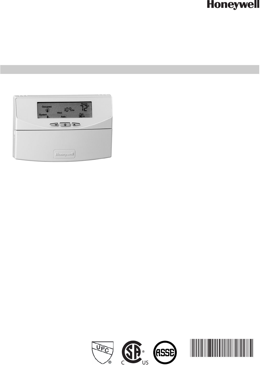
T7351 Commercial Programmable Thermostat
FOR SINGLE- OR MULTI-STAGE CONVENTIONAL/HEAT PUMP SYSTEMS
APPLICATION
The T7351 Commercial Programmable Thermostat controls
24 Vac commercial single zone heating, ventilating and air
conditioning (HVAC) equipment. The T7351 consists of a
thermostat and subbase. The thermostat includes the keypad
and display for 365-day programming. The subbase includes
equipment control connections. The subbase mounts on the
wall and the thermostat mounts to the subbase.
FEATURES
• Typically used in buildings (including: restaurants,
shopping malls, office buildings and banks) under
55,000 square feet.
• For single zone rooftop units, split systems, heat
pumps or hot/chilled water systems.
• 365-day programming.
• Two Occupied and two Not Occupied periods per day.
• Individual heat and cool setpoints available for
Occupied and Not Occupied periods.
• P+I+D control minimizes temperature fluctuations.
• Recovery ramp control automatically optimizes
equipment start times based on building load.
• Convenient overrides allow temporary setpoint
changes.
• Keypad multi-level lockout available with all models.
• Remote sensor capability for temperature (including
outdoor air and discharge air) and humidity sensors.
• Auxiliary subbase contact typically interface with a
Honeywell Economizer System (for total rooftop
control integration) or act as dehumidification output.
• Universal Versaguard Thermostat guards available.
Contents
Application ........................................................................ 1
Features ........................................................................... 1
Specifications ................................................................... 2
Ordering Information ........................................................ 2
Setting .............................................................................. 6
Installer Setup .................................................................. 7
Operation .......................................................................... 12
Troubleshooting Guide (Table 11) ..................................... 17
Wiring Diagram (Figures 14 and 15) ................................ 19


