Audio Command Center Series Manual — P/N 51889:E1 6/8/2010 85
Two Speaker Circuits on ACC-25/50 Application Examples
5.4 Two Speaker Circuits on ACC-25/50
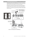
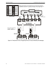
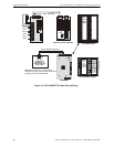
Single Output Zone, Five Input Channels - five messages (see Table 2.7 on page 37 for Message
Control switch settings).
This application consists of one ACC-25/50 Series with two speaker circuits which requires instal-
lation of the optional second amplifier. This configuration is suitable for small facilities requiring
no more than 50 watts of total output power. In this application, the addressable FACP utilizes
addressable control modules, which are connected to CMD1 through CMD5 inputs, to direct one of
the five voice messages to both
speaker circuits.
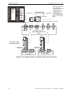
S3 DIP switches 1 and 3 are set to ON and 2 is set to OFF. This causes CMD1 to activate the Fire
Message, CMD2 to activate the Fire Alert Message, CMD3 to activate the Tornado Message,
CMD4 to activate the Chemical Spill Message and CMD5 to activate the All Clear Message. S5
and S6 DIP switches are set to ON which causes CMD1 and CMD2 inputs respectively to be acti-
vated by a contact closure.
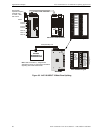
The system can also be manually activated via the keypad by selecting any of the Message push-
buttons on the keypad. Manually deactivating the speaker circuit is accomplished by pressing the
activated (illuminated) Audio On/Off push-button. To terminate the voice message, press the illu-
minated message push-button. Refer to the keypad example in Figure 5.3.
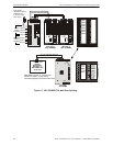
All Call Paging is possible by first pressing the All Call push-button on the keypad and then keying
the microphone to make an announcement. Refer to the keypad example in Figure 5.4


