Audio Command Center Series Manual — P/N 51889:E1 6/8/2010 63
Section 4: Operating Instructions
4.1 Switch Functions
4.1.1 Single Zone Operation (ACC-25/50, ACC-25/50ZS,
ACC-25/50ZST)
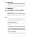
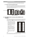
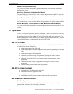
Figure 4.1 depicts Single Zone operation with the
maximum capacity of five messages. Single Zone
may be configured for two to five message control
(refer to Section 2, ”Field Programming” on page
32).
• ALL-CALL:
– used to select All Call function when ACC-
25/50 Series is programmed for Single Zone
operation. Selecting this button also activates
the Master Command Bus, which is used to
trigger Distributed Audio Panels. Single Zone
operation directs the same message to all
speaker circuits (S3 DIP switches 1, 2 and 3
set to one of the valid options other than all
OFF)
• AUDIO ON/OFF:
– used to indicate that audio is on when ACC-25/50 Series is programmed for Single Zone
operation (S3 DIP switches 1, 2 and 3 set to one of the valid options other than all OFF).
• MESSAGE 1 - used to manually transmit Message 1 over speaker circuit(s)
• MESSAGE 2 - used to manually transmit Message 2 over speaker circuit(s)
• MESSAGE 3 - used to manually transmit Message 3 over speaker circuit(s)
• MESSAGE 4 - used to manually transmit Message 4 over speaker circuit(s)
• MESSAGE 5 - used to manually transmit Message 5 over speaker circuit(s)
4.1.2 Dual Zone Operation (ACC-25/50 Only)
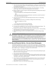
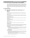
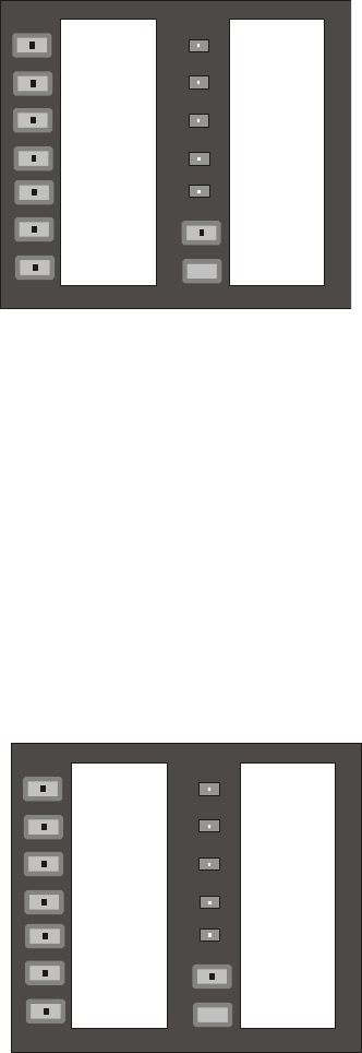
Figure 4.2 depicts Dual Zone Operation which sup-
ports the generation of one message only (refer to Sec-
tion 2, ”Field Programming” on page 32.
• ZONE 1:
– used to select Zone 1 when ACC-25/50 Series
is programmed for Dual Zone operation. Dual
Zone operation directs a single message to
either or both amplifier circuits (S3 DIP
switches 1, 2, and 3 set to OFF)
• ZONE 2:
– used to select Zone 2 when ACC-25/50 Series
is programmed for Dual Zone operation (S3
DIP switches 1, 2, and 3 set to OFF)
Figure 4.1 Controls and Indicators
Single Zone Operation
a
c
c
2
5
k
y
b
l
n
k
.
w
m
f
ALL-CALL
AUDIO ON/OFF
MESSAGE 1
MESSAGE 2
MESSAGE 3
MESSAGE 4
MESSAGE 5
POWER ON
SYSTEM
TROUBLE
MESSAGE
TROUBLE
GENERATOR
TONE
GENERATOR
TROUBLE
RECORD
PLAYBACK
TROUBLE
SILENCE
MICROPHONE
TROUBLE
Figure 4.2 Controls and Indicators
Dual Zone Operation
a
c
c
2
5
k
y
b
l
n
k
.
w
m
f
ZONE 1
ZONE 2
MESSAGE 1
POWER ON
SYSTEM
TROUBLE
MESSAGE
TROUBLE
GENERATOR
TONE
GENERATOR
TROUBLE
RECORD
PLAYBACK
TROUBLE
SILENCE
MICROPHONE
TROUBLE


