


INSTALLATION INSTRUCTIONS 3-phase R-22 Split System Heat Pump
506 01 5001 00 7
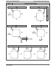
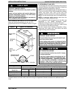
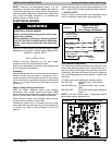
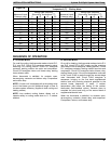
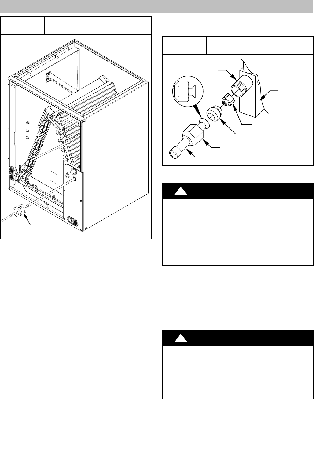
Figure 7
Liquid Line Filter-Drier
Installed at Indoor Coil
38-11-84
Filter-Drier
F. SERVICE VALVES
Service valves are closed and plugged from the factory.
Outdoor units are shipped with a refrigerant charge
sealed in the unit. Leave the service valves closed until all
other refrigeration system work is complete or the charge
will be lost. Leave the plugs in place until line set tubing is
ready to be inserted.
Heat pumps require a piston metering device in the liquid
service valve for proper heating operation. Piston and
retainer are shipped in the piston body of the liquid service
valve, temporarily held in place with a plastic cap. Do not
remove the plastic cap until line set tubing is ready to be
installed.
Refer to Figure 8 and follow these steps for piston
installation:
1. Remove plastic cap holding piston and retainer in
piston body of liquid service valve.
2. Check that piston size (stamped on side of piston)
matches with number listed on unit rating plate.
Return piston to piston body of liquid service valve
(either direction).
Return retainer to piston body.
NOTE: Small end of retainer fits inside piston body,
with O-ring sealing against inside of piston body
3. Find plastic bag taped to unit containing copper
adapter tube with brass nut.
4. Install adapter tube against retainer and thread
brass nut onto liquid service valve. Tighten nut
finger tight, then wrench additional ½ turn only.
Service valve bodies are brass and suction tube stub is
copper.
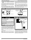
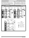
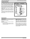
Figure 8
Liquid Service Valve with Piston
and Sweat/Flare Adapter Tube
PISTON BODY
PISTON
PISTON RETAINER
SWEAT/FLARE ADAPTER TUBE
LIQUID
SERVICE
VALVE
BRASS NUT
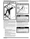
G. BRAZING CONNECTIONS
!
WARNING
FIRE HAZARD
Failure to follow this warning could result in per‐
sonal injury, death, and/or property damage.
Refrigerant and oil mixture could ignite and burn
as it escapes and contacts brazing torch. Make
sure the refrigerant charge is properly removed
from both the high and low sides of the system be‐
fore brazing any component or lines.
Clean line set tube ends with emery cloth or steel brush.
Remove any grit or debris.
Insert line set tube ends into service valve tube stubs.
Apply heat absorbing paste or heat sink product between
service valve and joint. Wrap service valves with a heat
sinking material such as a wet cloth.
Braze joints using a Sil-Fos or Phos-copper alloy.
!
CAUTION
PRODUCT DAMAGE HAZARD
Failure to follow this caution may result in product
damage.
Braze with Sil-Fos or Phos-copper alloy on cop‐
per-to-copper joints and wrap a wet cloth around
rear of fitting to prevent damage to TXV.