


INSTALLATION INSTRUCTIONS 3-phase R-22 Split System Heat Pump
506 01 5001 00 13
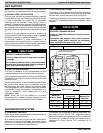
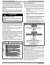
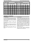
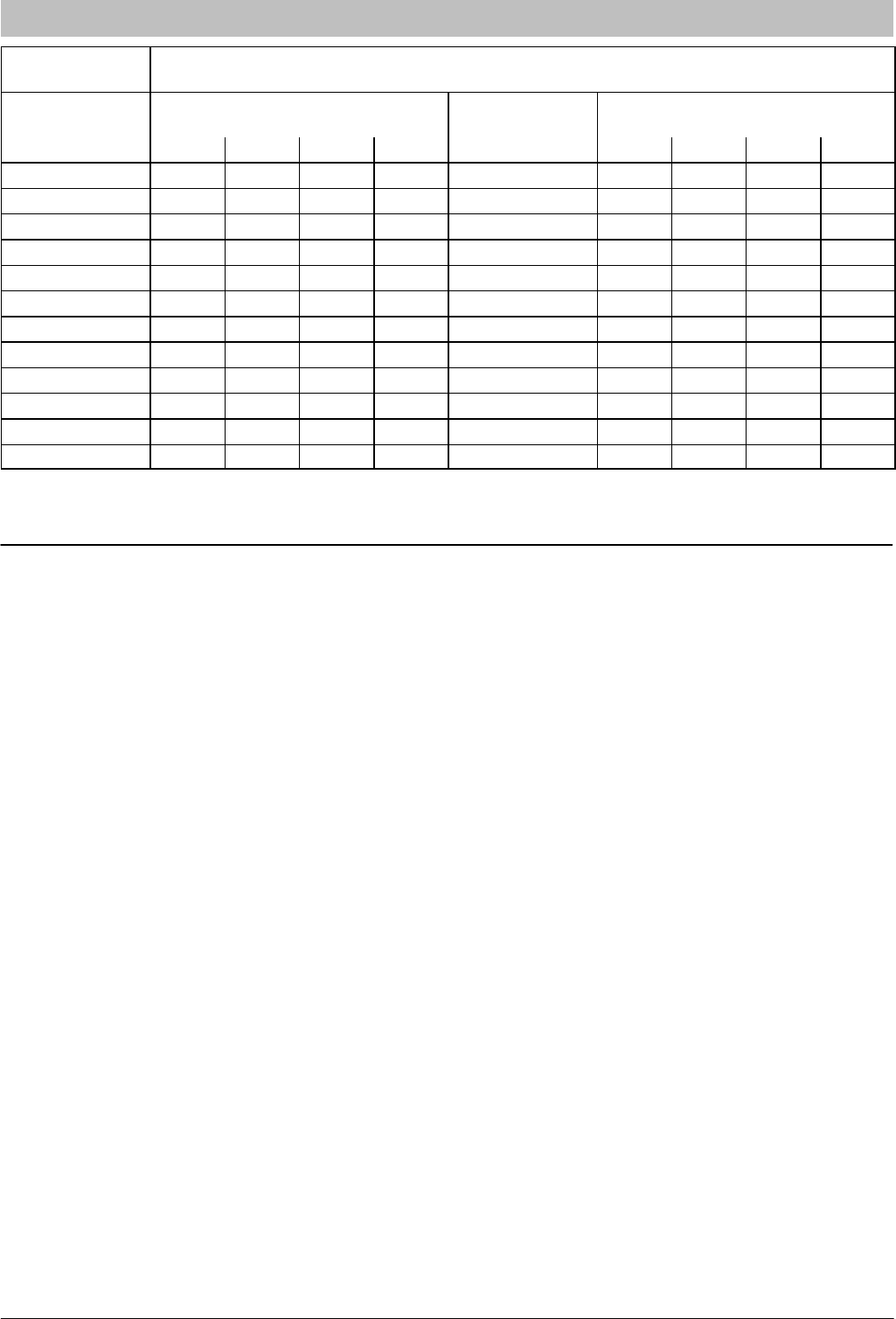
Figure 16
R-22 Required Liquid Line
Temperature (°F) - Cooling Mode
Measured Liquid
Pressure (psig)
Rating Plate (required)
Subcooling Temperature (°F)
Measured Liquid
Pressure (psig)
Rating Plate (required)
Subcooling Temperature (°F)
5 10 15 20 5 10 15 20
134 71 66 61 56 233 107 102 97 92
141 74 69 64 59 243 110 105 100 95
148 77 72 67 62 253 113 108 103 98
156 80 75 70 65 264 116 111 106 101
163 83 78 73 68 274 119 114 109 104
171 86 81 76 71 285 122 117 112 107
179 89 84 79 74 297 125 120 115 110
187 92 87 82 77 309 128 123 118 113
196 95 90 85 80 321 131 126 121 116
205 98 93 88 83 331 134 129 124 119
214 101 96 91 86 346 137 132 127 122
223 104 99 94 89 359 140 135 130 125
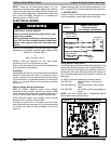
SEQUENCE OF OPERATION
A. COOLING MODE
On a call for cooling, the thermostat makes circuits R-O,
R-Y, and R-G. Circuit R-O energizes reversing valve,
switching it to cooling position. Circuit R-Y energizes
contactor, starting outdoor fan motor and compressor.
Circuit R-G energizes indoor unit blower relay, starting
indoor blower motor.
When thermostat is satisfied, its contacts open,
de-energizing contactor and blower relay. Compressor
and motors stop.
NOTE: If indoor unit is equipped with a time-delay relay
circuit, the blower runs an additional length of time to
increase system efficiency. (Applies to both cooling and
heating modes.)
NOTE: Low ambient cooling feature allows unit to
operate safely in cooling mode down to 0° F outdoor
ambient.
B. HEATING MODE
On a call for heating, the thermostat makes circuits R-Y
and R-G (circuit R-O is NOT made, and the reversing
valve stays in the de-energized, heating position). Circuit
R-Y energizes contactor, starting outdoor fan motor and
compressor. Circuit R-G energizes indoor blower relay,
starting blower motor. If the room temperature continues
to fall, circuit R-W2 is made through the second-stage
room thermostat bulb. Circuit R-W2 energizes a
sequencer, bringing on the first bank supplemental
electric heat and providing electrical potential to the
second heater sequencer (if used). If outdoor
temperature falls below the setting of the outdoor
thermostat (field-installed option), contacts close to
complete the circuit and bring on the second bank of
supplemental electric heat.
When the thermostat is satisfied, its contacts open,
de-energizing contactor, blower relay, and sequencer.
Compressor, motors, and heaters stop.