


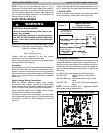
INSTALLATION INSTRUCTIONS 3-phase R-22 Split System Heat Pump
506 01 5001 00 5
!
CAUTION
PRODUCT DAMAGE HAZARD
Failure to follow this caution may result in product
damage.
Indoor coil and outdoor unit must be listed as a
certified combination (match) in the ARI Unitary
Directory of Certified Products.
Indoor coil must have R-22 specific, hard shut-off
TXV refrigerant metering device.
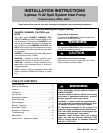
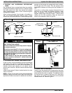
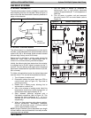
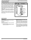
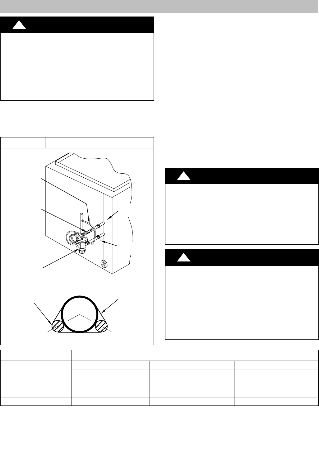
When installing a hard shut-off TXV on an indoor coil,
follow the instructions provided with the new TXV.
A typical hard shut-off TXV installation is shown in Figure
3.
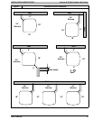
Figure 3 Typical TXV Installation
HARD
SHUT-OFF
TXV
SENSING
BULB
EQUALIZER
TUBE
8 O'CLOCK 4 O'CLOCK
STRAP
SENSING BULB
(EITHER SIDE)
SUCTION
TUBE
INDOOR
COIL
SUCTION
TUBE
LIQUID
TUBE
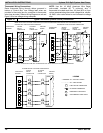
B. REFRIGERANT LINE SETS
The refrigerant line set must be properly sized to assure
maximum efficiency and proper oil circulation. Select line
set tube diameters as specified in Figure 4.
NOTE: If the line set actual length is to exceed 80 feet, or
if there is more than 20 feet vertical separation between
outdoor and indoor units, refer to the Long Line
Application Guidline document for additional instructions.
NOTE: Line set actual length must not exceed 200 feet.
NOTE: A crankcase heater must be used when the
refrigerant line length exceeds 80 feet.
If it is necessary to add refrigerant line in the field, use
dehydrated or dry, sealed, deoxidized, copper
refrigeration tubing. Do not use copper water pipe.
Do not remove rubber plugs or caps from copper tubing
until connections are ready to be made.
Be extra careful when bending refrigeration tubing.
Tubing can “kink” easily, and if this occurs, the entire
length of tubing must be replaced.
!
WARNING
PERSONAL INJURY HAZARD
Failure to follow this warning could result in per‐
sonal injury and/or death.
Relieve pressure and recover all refrigerant before
servicing existing equipment, and before final unit
disposal. Use all service ports and open all flow-‐
control devices, including solenoid valves.
!
CAUTION
UNIT OPERATION HAZARD
Failure to follow this caution may result in improp‐
er product operation.
Do not leave system open to atmosphere any lon‐
ger than absolutely required for installation. Inter‐
nal system components - especially refrigerant
oils - are extremely susceptible to moisture con‐
tamination. Keep ends of tubing sealed during
installation until the last possible moment.
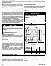
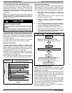
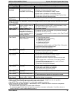
Figure 4 R-22 Line Set Tube Diameter (Liquid Tube Always a"” dia.)
Model Size
Service Valve Fittings Line Set < 80 feet long Line Set 80 - 200 feet long
Liquid Suction Suction Line Diameter Suction Line Diameter
36 (3 ton) a” w” w” d”
42 (32 ton), 48 (4 ton) a” d” d” !8”
60 (5 ton) a” d” !8” !8”
NOTE: If the line set actual length is to exceed 80 feet, or if there is more than 20 feet vertical separation
between outdoor and indoor units, refer to the Long Line Application Guideline document for additional instruc‐
tions.