


INSTALLATION INSTRUCTIONS 3-phase R-22 Split System Heat Pump
16 506 01 5001 00
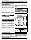
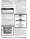
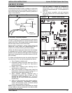
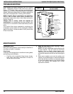
Figure 19 Comfort Alertt Diagnostics (some models)
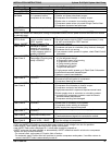
Miswired Module Indication Troubleshooting Information
Green LED is not on, module
does not power up
Determine if both R and C module terminals are connected. Verify voltage is
present at module's R and C terminals.
Green LED intermittent, mod‐
ule powers up only when com‐
pressor runs
Determine if R and Y terminals are wired in reverse. Verify module's R and C
terminals have a constant source.
TRIP LED is on but system
and compressor check OK
Verify Y terminal is wired properly per OEM wiring diagram. Verify voltage at
contactor coil falls below 0.5VAC when off. Verify 24VAC is present across Y and
C when thermostat demand signal is present. If not, R and C are reverse wired.
TRIP LED and ALERT LED
flashing together
Verify R and C terminals are supplied with 19-28VAC.
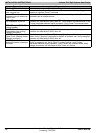
ALERT Flash Code 3
(Compressor short cycling)
displayed incorrectly
Verify Y terminal is connected to 24VAC at contactor coil. Verify voltage at
contactor coil falls below 0.5VAC when off.
ALERT Flash Code 5 or 6
(Open Circuit, Missing Phase)
displayed incorrectly
Check that compressor T1 and T3 wires are through module's current sensing
holes. Verify Y terminal is connected to 24VAC at contactor coil. Verify voltage at
contactor coil falls below 0.5VAC when off.
ALERT Flash Code 8
(Welded Contactor) displayed
incorrectly
Determine if module's Y terminal is connected. Verify Y terminal is connected to
24VAC at contactor coil. Verify 24VAC is present across Y and C when
thermostat demand signal is present. If not, R and C are reversed wired. Verify
voltage at contactor coil falls below 0.5VAC when off. Review.
International Comfort Products, LLC
Lewisburg, TN 37091