


INSTALLATION INSTRUCTIONS 3-phase R-22 Split System Heat Pump
4 506 01 5001 00
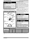
UNIT SUPPORT
NOTE: Unit must be level | 2 degrees (a inch rise or fall
per foot of run) or compressor may not function properly.
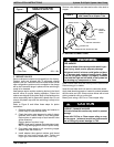
A. GROUND LEVEL INSTALLATION
The unit must be level and supported above grade by
beams, platform, or a pad. Platform or pad can be of open
or solid construction but should be of permanent
materials such as concrete, bricks, blocks, steel, or
pressure- treated timbers approved for ground contact.
Soil conditions must be considered so that the platform or
pad does not shift or settle and leave the unit partially
supported. Minimum pad dimensions are shown in Figure
2.
If beams or an open platform are used for support, it is
recommended that the soil be treated or area be graveled
to reduce the growth of grasses and weeds.
To minimize vibration or noise transmission, it is
recommended that supports not be in contact with the
building structure. However, slabs on grade constructions
with an extended pad are normally acceptable.
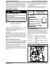
!
CAUTION
PROPERTY DAMAGE HAZARD
Failure to follow this caution may result in proper‐
ty damage.
Top surface of platform must be above estimated
snowfall level to prevent snow blocking coil and to
allow water melt to drain from unit.
B. ROOF TOP INSTALLATION
This type of installation is not recommended on wood
frame structures where low noise levels are required.
Supporting structure or platform for the unit must be level.
If installation is on a flat roof, locate unit minimum 6 inches
above roof level.
Place the unit over one or more load bearing walls. If there
are several units, mount them on platforms that are
self-supporting and span several load bearing walls.
These suggestions are to minimize noise and vibration
transmission through the structure. If the structure is a
home or apartment, avoid locating the unit over
bedrooms or study.
NOTE: When unit is to be installed on a bonded
guaranteed roof, a release must be obtained from the
building owner to free the installer from all liabilities.
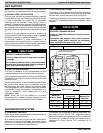
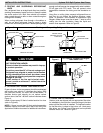
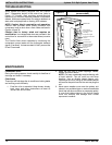
C. FASTENING UNIT DOWN
If conditions or local codes require the unit be attached in
place, remove the knockouts in the base pan and install
tie down bolts through the holes (refer to Figure 2).
Contact local distributor for hurricane hold-down details
and the P.E. (Professional Engineer) certification, when
required.
!
CAUTION
PROPERTY DAMAGE HAZARD
Failure to follow this caution may result in proper‐
ty damage.
Inadequate unit support may cause excessive
vibration, noise, and/or stress on the refrigerant
lines, leading to refrigerant line failure.
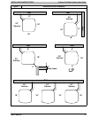
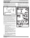
Figure 2 Tie Down Knockouts
Base
Pan
Depth
C
B
A
Base Pan Width
a” dia. Tie Down Knockouts
In Base Pan (2 places)
VIEW
FROM
TOP
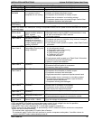
Base Pan
Width x Depth
Tie Down
Knockouts
Minimum
Mounting Pad
Dimensions
A B C
@%w” ~ @^c” (8” $v” @!4” @^ X~ @^2”
#!x” ~ #@v” (8” ^b” @$n” #!2 ~ #@2”
#%” ~ #^b” (8” ^b” @*v” #%” ~ #^2”
REFRIGERATION SYSTEM
A. COMPONENT MATCHES
Check to see that the proper system components are in
place, especially the indoor coil.
R-22 outdoor units can only be used with R-22 specific
indoor coils. If there is a refrigerant mis-match, consult
the indoor coil manufacturer to determine if a refrigerant
conversion kit is available for the indoor coil.
This outdoor unit is designed for use only with indoor coils
that utilize a hard shut-off TXV refrigerant metering
device. If any other type of metering device is installed on
the indoor coil, consult the indoor coil manufacturer to
determine if a hard shut-off TXV conversion kit is
available.