


FP USER INSTRUCTIONS ENGLISH 71576286 - 07/06
Page 20 of 35
It is strictly forbidden to open switch
cupboards, switch boxes, or all other live electric
equipment. If it is necessary to open them in order to
take readings, to carry out tests or adjustments for
example, only a skilled technician may do them with
adapted tools. Make sure that physical protections
against electrical risks are used.
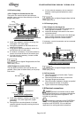
5.5.4 Bearings
If the pumps are working in a potentially
explosive atmosphere, temperature or vibration
monitoring at the bearings is recommended.
If bearing temperatures are to be monitored it is
essential that a benchmark temperature is recorded
at the commissioning stage and after the bearing
temperature has stabilized.
Record the bearing temperature (t) and the
ambient temperature (ta)
Estimate the likely maximum ambient
temperature (tb)
Set the alarm at (t+tb-ta+5) C [(t+tb-ta+10) F]
and the trip at 100 C (212 F) for oil lubrication
and 105 C (220 F) for grease lubrication
It is important, particularly with grease lubrication, to
keep a check on bearing temperatures. After start up
the temperature rise should be gradual, reaching a
maximum after approximately 1.5 to 2 hours. This
temperature rise should then remain constant or
marginally reduce with time.
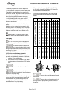
5.5.5 Normal vibration levels, alarm and trip
For guidance, pumps generally fall under a
classification for rigid support machines within the
International rotating machinery standards and the
recommended maximum levels below are based on
those standards.
Alarm and trip values for installed
pumps should be based on the actual
measurements (N) taken on site on the bearing
housings of the pump in the fully commissioned as
new condition.
The example (N) value is given for the preferred
operating flow region (typically this may extend to 70
to 120 % of the pump best efficiency point); outside
the preferred flow region the actual vibration
experienced may be multiplied by up to 2.
These standard values can vary with the rotational
speed and the power absorbed by the pump. For
any special case, do not hesitate to consult us.
Measuring vibration at regular intervals will then
show any deterioration in pump or system operating
conditions.
Vibration Velocity - unfiltered
Horizontal Configuration
mm/s (in./s) r.m.s.
Normal N 5.6 (0.22)
Alarm N x 1.25 7.1 (0.28)
Shutdown Trip N x 2.0 11.2 (0.44)
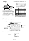
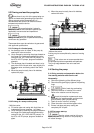
5.5.6 Stop/start frequency
Pump sets are normally suitable for the number of
equally spaced stop/starts per hour shown in the
table below. Check actual capability of the driver and
control/starting system before commissioning.
Motor rating kW (hp)
Maximum stop/starts
per hour
Up to 15 (20) 15
Between 15 (20) and 90 (120) 10
90 (120) to 150 (200) 6
Above 150 (200) Refer
Where duty and standby pumps are installed it is
recommended that they are run alternately every
week.
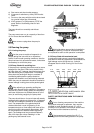
5.6 Stopping and shutdown
5.6.1 Stopping and restarting in continuous
running
According to hydraulic conditions of the installation
and its automation degree, stop and restart
procedures can have different forms. Nevertheless
all of them must respect imperatively the following
rules:
Stopping:
a) Avoid that the unit turns in the opposite direction
to the normal running.
b) Make sure that the discharge line pressure does
not reach the foot valve.
c) Avoid a continuous running below the authorized
flow rate (see § 5.4.2).
Restart:
a) Ensure that the pump is completely full of liquid.
b) Ensure a continuous supply with a sufficient
available NPSH.
c) Ensure a backpressure so that the motor power
is not in excess.
d) Respect the starting frequency
imposed by the motor manufacturer.
e) Protect the pump against water hammer
when stopping or starting.