


FP USER INSTRUCTIONS ENGLISH 71576286 - 07/06
Page 16 of 35
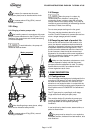
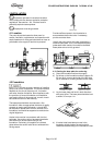
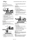
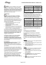
4.5.2 Suction piping
4.5.2.1 Design of a flooded suction line
The suction line must be as short and direct as
possible, never mount an elbow directly on the inlet
flange of the pump.
Valve
Non-return valve
Continous flow
valve
Flooded suction configuration
a) Avoid sharp elbows or sudden narrowing. Use
convergent 20° (total angle).
b) Arrange the pipework so that there are no air
pockets (no bulges).
c) If high points cannot be avoided in suction line,
provide them with air relief cocks.
d) If a strainer is necessary, its net area should be
three or four times the area of the suction pipe.
e) If an inlet valve is necessary, choose a model
with direct crossing.
Do not tighten flanges before the final
check (see § 4.5.4).
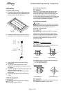
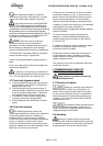
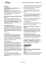
4.5.2.2 Design of a suction lift line
The inlet pipe must be as short and as direct as
possible, never place an elbow directly on the pump
inlet nozzle.
Valve
Non-return valve
I:
SUFFICIENT IMMERSION
Valve strainer
I 3 x D
Sump suction configuration
a) Avoid sharp elbows or sudden narrowing. Use
convergent 20° (total angle) with upright
generating.
b) Arrange that the suction pipework is inclined
upwards towards the pump ensuring that there
are no peaks.
c) If a foot valve is necessary, do not oversize it
because it would generate pulsations (valve
beating).
Do not tighten flanges before the final
check (see § 4.5.4).
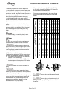
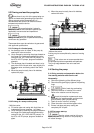
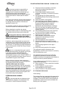
4.5.3 Discharge piping
4.5.3.1 Design of a discharge line
a) If discharge line is provided with a divergent, its
total angle will be between 7° and 12°.
b) Install the discharge valve after the non-return
valve downstream.
c) The non-return valve will be set in the discharge
pipe to protect the pump from any excessive
pressure surge and from reverse rotation.
If necessary, a control manometer can be connected
on the pipework.
Control manometer
Setting of the control manometer
Do not tighten flanges before the final
check (see § 4.5.4).
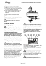
4.5.4 Final checks
a) Check the tightening of anchor bolts. Tighten
them if necessary.
b) Check that protective covers on suction and
discharge flanges are removed.
c) Check that holes of pipework flanges are parallel
and correspond to those of the pump.
d) Tighten suction and discharge flanges.
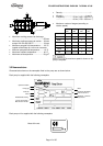
4.6 Electrical connections
Electrical connections must be made
by a qualified Electrician in accordance with relevant
local national and international regulations. This
includes any grounding.
It is important to be aware of the EUROPEAN
DIRECTIVE on potentially explosive areas where
compliance with IEC60079-14 is an additional
requirement for making electrical connections.