


FP USER INSTRUCTIONS ENGLISH 71576286 - 07/06
Page 15 of 35
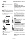
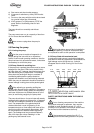
If necessary, improve the machine alignment:
Complete unit mounted on common base plate:
The machines are first aligned accurately in our
workshops. Usually, any misalignment observed on-
site is due to a wrong adjustment under the base
plate (disturbed during transport or because of
forces exerted by the pipework). It is only necessary
to rectify the adjustment under base plate. If it
proves to be insufficient, modify the motor and the
pipeworks adjustment.
Pump and motor mounted on individual base
plates:
Machines are (or must be) first mounted on their
own base plate in the workshop. Once the pump is
set, it will be regarded as the fixed piece. Any
alignment necessary shall be carried out on the
motor.
Never connect the electric motor
before the setting has been completely finished.
4.5 Piping
The user must verify that the equipment is
isolated from any external sources of vibration.
Protective covers are fitted to the
pipe connections to prevent foreign bodies entering
during transportation and installation. Ensure that
these covers are removed from the pump before
connecting any pipes.
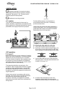
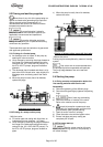
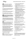
4.5.1 Suction and discharge pipework
The dimensions of the pipes do not directly depend
on suction and discharge diameters of the pump.
a) First, choose a flow speed < 2 m/s at suction,
and about 3 m/s at discharge.
b) Take into account the available NPSH, which
must be superior to the required NPSH of the
pump.
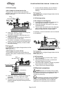
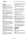
Never use pump as a support for
piping.
Do not mount expansion joints in
such a way that their force, due to internal pressure,
may act on the pump flange.
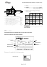
Maximum forces and moments allowed on the pump
flanges vary with the pump size and type. These
external strains may cause misalignment, hot
bearings, worn couplings, vibrations and the
possible failure of the pump casing.
When designing the pipes (§ 4.5.2.1, § 4.5.2.2, §
4.5.3.1) take necessary precautions in order not to
exceed maximum allowed strains.
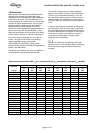
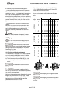
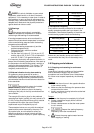
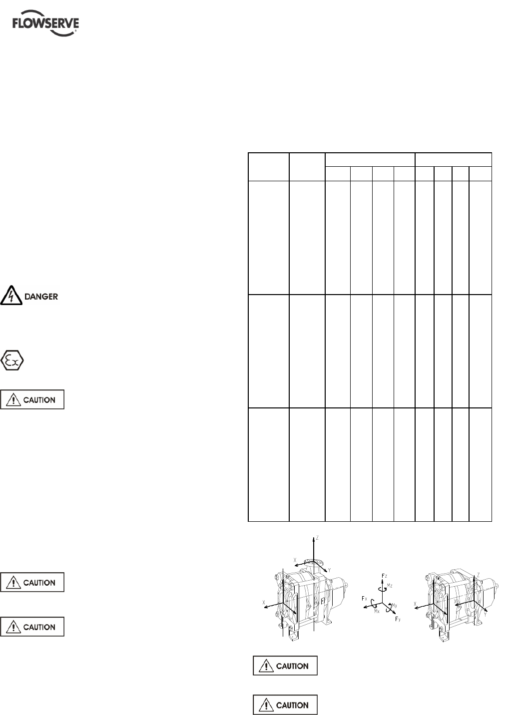
Forces and moments applied to the pump flanges
must never exceed the values shown in the table
below:
DN
Forces (daN) Moments (daN.m)
Pipe
Layout flanges
F
Y
F
Z
F
X F
M
Y
M
Z
M
X M
40 30 40 35 60 23 27 34 49
50 40 50 45 80 27 30 37 54
65 50 68 58 102 30 33 40 60
80 60 75 70 120 32 36 44 65
100 80 100 90 160 36 41 50 74
125 100 125 110 200 44 52 63 92
150 120 150 135 240 53 62 75 110
Vertical pipe
perpendicular to the shaft
200 162 200 180 314 69 79 97 144
40 40 30 35 60 23 27 34 49
50 50 40 45 80 27 30 37 54
65 68 50 58 102 30 33 40 60
80 75 60 70 120 32 36 44 65
100 100 80 90 160 36 41 50 74
125 125 100 110 200 44 52 63 92
150 150 120 135 240 53 62 75 110
Horizontal pipe
perpendicular to the shaft
200 200 162 180 314 69 79 97 144
40 35 30 40 60 23 27 34 49
50 45 40 50 80 27 30 37 54
65 58 50 68 102 30 33 40 60
80 70 60 75 120 32 36 44 65
100 90 80 100 160 36 41 50 74
125 110 100 125 200 44 52 63 92
150 135 120 150 240 53 62 75 110
Pipe parallel to the axis
200 180 162 200 314 69 79 97 144
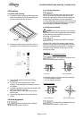
Ensure piping and fittings are flushed
before use.
Ensure piping for hazardous liquids is
arranged to allow pump flushing before removal of
the pump.