


6
• Do not use vaseline, oils, other hydrocarbon lubricants or
spray silicone anywhere. A silicon lubricant may be used on
black o-rings but is not necessary. Avoid any type of
lubricants, including silicone, on red or clear lip seals.
• Do not use pipe dope or other sealants on threads. Only
teflon tape may be used on threads. Teflon tape is not
necessary on the nut connection or caps because of o-ring
seals.
• The pipe size for the drain line should be a minimum of 3/4”.
Backwash flow rates in excess of 7 gpm or length in excess
of 20’ require 1” drain line.
1. Place the conditioner where you want to install it, making
sure it is on a clean, level and firm base.
2. Do all necessary plumbing (inlet to inlet, outlet to outlet and
drain line to drain). The control valve, fittings and/or bypass
are designed to accommodate minor plumbing
misalignments but are not designed to support the weight of
a system or the plumbing.
3. When assembling the installation fitting package (inlet and
outlet), connect the fitting to the plumbing system first and
then attach the nut, split ring and o-ring. Heat from soldering
or solvent cements may damage the nut, split ring or o-ring.
Solder joints should be cool and solvent cements should be
set before installing the nut, split ring and o-ring. Avoid
getting primer and solvent cement on any part of the o-rings,
split rings, bypass valve or control valve.
4. A jumper ground wire should be installed between the
inlet and outlet pipe whenever the metallic continuity of
a water distribution piping system is interrupted. In-
stall grounding strap on metal pipes.
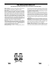
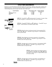
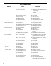
5. The drain connection may be made using either 5/8” polytube
(See figure 6a, page 5) or a 3/4” female adapter. If
soldering, joints near the drain must be done prior to
connecting the drain line flow control fitting. Leave at least
6” between the drain line control fitting and solder joints
when soldering pipes that are connected on the drain line
control fitting. Failure to do this could cause interior damage
to the drain line flow control fitting.
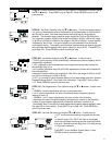
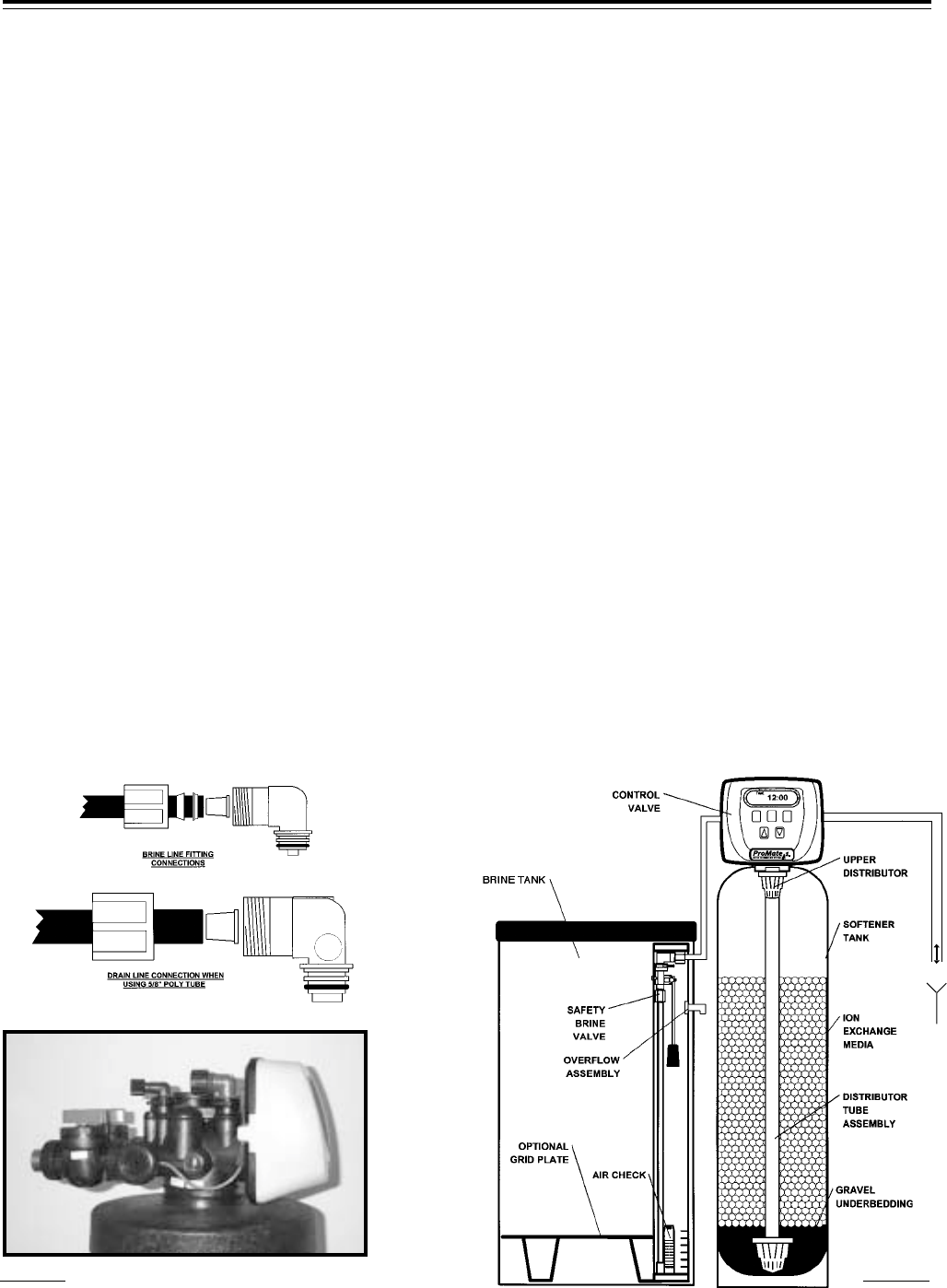
6. The brine refill flow control assembly is installed in an easy
to access refill elbow located on top of the control valve. The
refill flow control assembly is attached to the control valve
with a locking clip. The locking clip allows the elbow to
rotate 270 degrees so the outlet can be orientated towards
the saltkeeper.
7. Connect the brine line found in the brine tank to the brine
connection on the control valve. The control valve has a
standard refill elbow which a 3/8” flexible tube can be
connected, see figure 6a, page 5. (An optional elbow can
be ordered which accommodates a 1/2” flexible tube for a
high regenerant draw rate situation). Both elbows use the
same refill flow control and retainer. Do not connect the
other end of the brine line to the safety brine valve in the
brine tank at this time. Make sure the floor is clean beneath
the salt tank and that it is level and smooth.
8. A 1/2” (inside diameter) gravity drain line may be connected
to the overflow fitting on the side of the brine tank. This
overflow is in case of a malfunction in the brine shut off. If
the unit is installed where water may flow in the event of an
overflow and cause water damage, connect a length of
flexible tubing and run to a drain below the level of the
overflow. (Do not connect the tubing to the drain line on
the control valve. Do not run tubing above overflow
height at any point.)
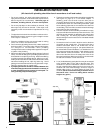
INSTALLATION INSTRUCTIONS
(All electrical & plumbing should be done in accordance to all local codes)
Figure 6a
Drain
Connection
Brine Line
Connecton
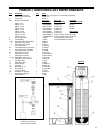
Figure 6b
1”