


8
Motor Heater
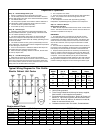
Model No. of Amps. Amps.
Size Motors A* B* A* B*
09 1 0.8 0.4 4.13 2.07
12 2 1.6 0.8 5.22 2.61
16 2 1.6 0.8 6.09 3.04
21 1 1.0 0.5 9.57 4.78
28 3 - 1.2 - 5.7
35 2 - 1.0 - 7.0
53 3 - 1.5 - 8.5
Replacement Parts
Part
115 Volt 208-230 Volt
Description 09 12 16 21 09 12 16 21 28 35 53
Motor 25300701 25300701 25300701 25303201 25300801 25300801 25300801 25303301 25300801 25303301 25303301
Fan Blade 5101B 5101B 5101B 23100201 5101B 5101B 5101B 23100201 5101B 23100201 23100201
Fan Guard 5054D 5054D 5054D H50328 5054D 5054D 5054D H50328 5054D H50328 H50328
Heater 4539N 4540N 4541N 4545N 4542N 4543N 4544N 4546N H50097 24700701 24700702
Heater Clip 5543J 5543J 5543J 5543J 5543J 5543J 5543J 5543J H50039 5543J 5543J
Defrost Control 5709L 5709L 5709L 5709L 5709L 5709L 5709L 5709L 5709L 5709L 5709L
Mount 91179001 91179001 91179001 23101401 91179001 91179001 91179001 23101401 91179001 23101401 23101401
Step “A” - Normal Refrigeration Cycle
1. Power is supplied to N and 4 terminals by the timer.
2. The fan delay and defrost termination thermostat is closed in
the fan delay position and open in the defrost termination position.
3. The defrost heater is off.
4. The compressor operates in accordance with the demands of
the refrigeration system temperature and/or pressure controls.
5. The unit cooler fan operates continually.
6. Frost builds up slowly on the evaporator.
Step “B” - Defrost Cycle
1. Defrosting of the evaporator is started automatically by the
timer at predetermined times - typical settings of the timer would
be 1 to 3 defrost periods per 24 hours.
2. The timer mechanically opens switch “A” which breaks the
circuit to the compressor and evaporator fan motors, thereby
shutting them off, and closes switch “B,” thereby permitting current
to flow to the heater.
3. The heater recessed in slots, gives up heat directly to the fins
of the evaporator. This heat raises coil and refrigerant temperature
to 32
º
F causing the frost to melt.
4. Frost on the evaporator is melted and defrost water drips into
the heated drain pan and flows down the drain.
5. When frost has completely melted from the coil, the coil starts
to warm up beyond 32
º
F.
Step “C” - Coil Re-Cooling Cycle
1. When the coil warms up to 55
º
F, the defrost termination
thermostat closes which allows the current to flow to the solenoid
in the timer, which then energizes and trips the timer switch back
to its normal position (switch “A” closed, switch “B” open). The fan
delay portion of this thermostat is now open.
2. The compressor now starts.
3. Then fan motors remain off because the fan delay thermostat
is open. This prevents warm air from being blown into the
refrigerated space.
4. The evaporator coil cools down approaching operating
temperature. Superheated gas only passes to the compressor.
Step “D” - Return to Normal
Refrigeration Operation
1. When the coil temperature reaches 35
º
F, the fan control switch
closes. This allows current to flow to the fan motor and the unit is
now back in operation as in Step “A.”
IMPORTANT
1. On initial “pull down” of a warm box, the fan will not start
until coil temperature reaches approximately 35
º
F. If box is still
comparatively warm (60
º
F) when the fan starts, then blowing this
warm air over the coil may cause it to warm up to 55
º
F and thus
stop the fan. Therefore, fan may recycle several times on initial
“pull down.”
2. The timer has an adjustable fail-safe feature which will return
the system to the refrigeration cycle at the end of a predetermined
time (factory set at 24 minutes) if automatic control devices fail.
3. Frequent defrost periods are not necessary! The determining
factor for number of defrosts per day is the frost load. When frost
“build-up” results in a loss of refrigeration capacity, then a defrost
is required. One to three defrosts per day are recommended.
4. A low temperature thermostatic expansion valve with pressure
limiting feature is desirable for use with these units. Such a valve
prevents feeding of refrigerant to the coil during the defrost cycle.
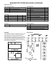
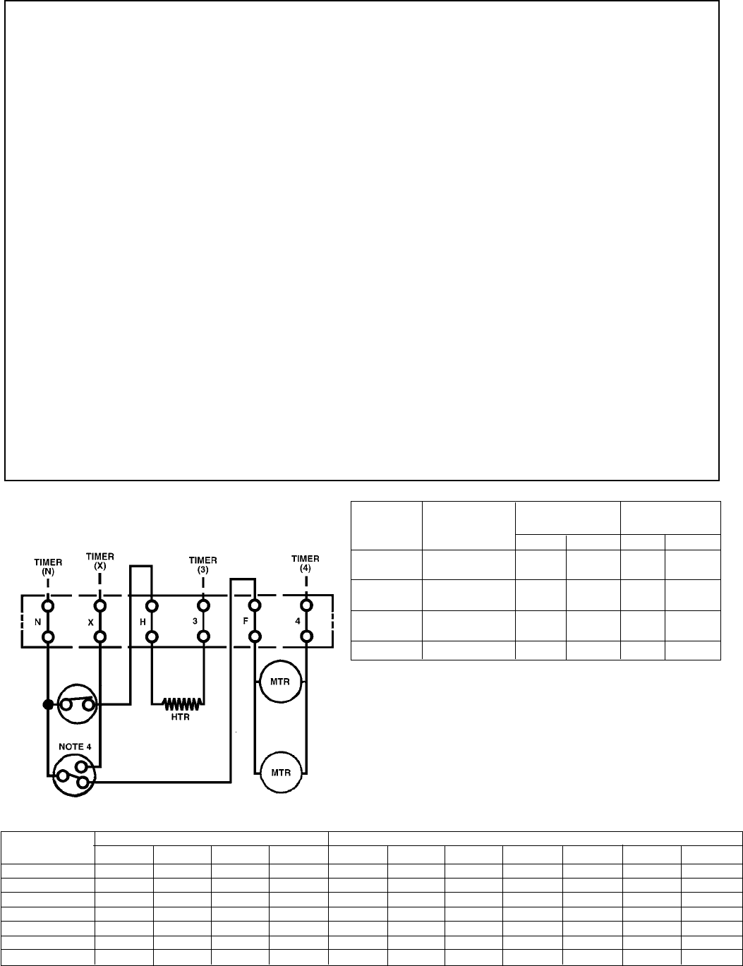
Sequence of Operation
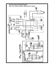
Typical Wiring Diagram for Thin Profile
Electric Defrost Unit Cooler
1. Use copper conductors only.
2. Unit must be grounded.
3. Timer-Paragon Model 8145-20 may be factory supplied,
field installed, or field supplied and installed.
4. Fan delay and defrost termination - Red to N, Brown to X,
Black to F. Fans will not operate until thermostat resets.
5. Heater limit: Red to N, White to H omitted on model 28;
heater is connected directly to N.
6. *Indicates electrical code: A=115/60/1, B=208-230/60/1.