


5
Replacement Parts
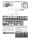
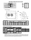
Always give complete model numbers and serial numbers when ordering parts.
General Information (contʼd)
NOTE: After correcting faulty condition it is
essential that the coil and unit be free of
ice before placing unit back on automatic
operation.
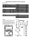
The electric defrost units are relatively simple and trouble-free in operation:
Timer
If the system does not go through its proper sequence , check timer operation through a defrost cycle. Check for loose
wires or terminals. Before replacing timer, check other components.
Operation of Paragon Timer
To set time of day grasp knob which is in the center of the inner (fail-safe) dial and rotate it in a counter-clockwise direction.
This will cause the outer (24 hour) dial to revolve. Line up the correct time of day on the outer dial with the time pointer.
Do not try to set the time control by grasping the other (24 hour) dial. Place pins in the outer dial at the time of day that
defrost is required.
Operation of Grasslin Timer
To set the time, turn the minute hand clockwise until the time of day (and AM or PM) on the outer dial is aligned with the
triangle marker on the inner dial. Do not rotate minute hand counter-clockwise. Move the white tab (tripper) on the
outer dial outward at each desired initiation time. Each white tab (tripper) is a 15 minute interval and provides 15 minutes
of defrost. For longer defrost duration, move additional tabs (following in time) from the initiation tab. For example, if a
45 minute defrost is to start at 7:00 AM, move the tabs outward that lie between 7:00 - 7:15, 7:15 - 7:30 and 7:30 - 7:45
on the AM side of the dial. The defrost will initiate at 7:00 AM and time terminate at 7:45 AM (if temperature termination
does not occur first).
Fan Motor
If the motor does not operate or it cycles on thermal overload, remove motor leads from terminal block and apply correct
voltage across the leads. If motor still does not operate satisfactorily, it must be replaced. Before starting the unit, rotate
fan blades to make sure they turn freely and have sufficient clearance.
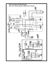
Fan Delay & Defrost Termination Control
This control is a single pole double throw switch. The red lead wire is wired to common. The black wire is wired in series
with the fan motors. The brown wire is wired in series with the defrost termination solenoid in the timer. The brown and
red contacts close and the black and red contacts open when the temperature is above 55
º
F. The black and red contacts
close and the brown and red contacts open when the temperature is below 35
º
F.
On initial “pull down” of a warm box the fan will not start until the coil temperature reaches approximately 35
º
F. If the box
is still comparatively warm (60
º
F) when the fan starts, then blowing this warm air over the coil may cause it to warm up
to 55
º
F and thus stop the fan. Therefore, the fan may recycle on initial “pull down.” This control cannot be adjusted.
If the fan motor fails to start when the control is below 35
º
F, disconnect the fan motor leads and check the motor as
described for fan motors. Also check whether current is being supplied at “N” and “4” from the timer. The fan delay
control must be below 35
º
F when checking for a closed circuit.
Defrost Heater
If unit shows very little or no defrosting and does not heat, disconnect heater and check to find if it is burned out. To test,
apply correct voltage across heater or use continuity flashlight battery tester.
Drain Pan
If drain pan has an ice build-up, drain line may be frozen. The drain line should be pitched sharply and exit cabinet
as quickly as possible. Sometimes location and ambient at the drain outside of cabinet may cause freeze-up. A drain
line heater may be required to correct the freeze-up. Any traps in the drain line must be located in a
warm ambient.
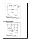
ELECTRIC DEFROST TROUBLESHOOTING