


Heat & Glo • ST-42TVFL-IPI • 455-902 Rev. C • 12/07
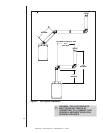
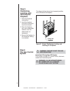
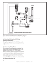
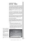
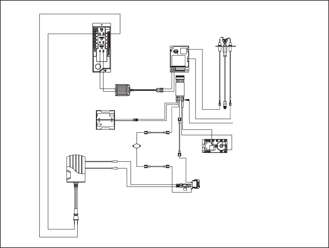
Figure 10. Intermittent Pilot Ignition (IPI) Wiring Diagram
For Intermittent Pilot Ignition (IPI) Wiring
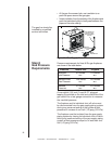
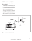
Appliance Requirements
This appliance requires that 110-120 VAC be wired to
the junction box. Maintain correct polarity when wiring
the junction box.
Operation using Battery Power
This fireplace has an optional battery operation. The
system is fully functional with the use of two “D” size
batteries without ordinary 110-120 VAC power.
Wiring to the battery pack should be left disconnected
in order to conserve battery life. In the case of a loss of
power, simply connect red and black wire leads to
activate battery power (connect red to red, black to
black). The fireplace can be used as necessary. Once
power (110 VAC) is restored, disconnect red and black
wire leads to extend battery life.
GREEN
ORANGE
ORANGE
WHITE
GROUND TO FIREPLACE CHASSIS
INTERMITTENT
PILOT IGNITOR
IGNITION
MODULE 3 VAC
TRANSFORMER 3V
BATTERY PACK
HI LIMIT SENSOR
PIGTAIL
CONNECTOR
VALVE
JUNCTION BOX
BROWN
BROWN
BLACK
RED
I
S
REMOTE
RECEIVER
*Shown with optional remote control receiver.
20