


Heat & Glo • SL-350TRS-C, SL-550/750TRS-IPI-D • 2065-985 Rev. J • 5/06
42
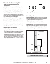
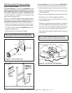
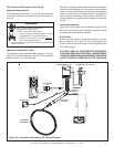
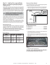
Step 9. Finishing
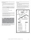
Figure 38 shows the minimum vertical and corresponding
maximum horizontal dimensions of appliance mantels or
other combustible projections above the top front edge of
the appliance. See Figures 4 and 5 for other appliance
clearances.
Only non-combustible materials may be used to cover the
black appliance front.
WARNING: WHEN FINISHING THE APPLI-
ANCE, NEVER OBSTRUCT OR MODIFY THE
AIR INLET/OUTLET GRILLES IN ANY MAN-
NER.
!
Figure 38.
Minimum Vertical and Maximum Horizontal
Dimensions of Combustibles above Appliance
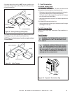
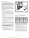
CAUTION: IF JOINTS BETWEEN THE FINISHED WALLS
AND THE APPLIANCE SURROUND (TOP AND SIDES)
ARE SEALED, A 300°
F. MINIMUM SEALANT MATE-
RIAL MUST BE USED. THESE JOINTS ARE NOT RE-
QUIRED TO BE SEALED. ONLY NON-COMBUSTIBLE
MATERIAL (USING 300° F. MINIMUM ADHESIVE, IF
NEEDED) CAN BE APPLIED AS FACING TO THE APPLI-
ANCE SURROUND. SEE THE DIAGRAM BELOW.
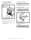
Hearth Extensions
A hearth extension may be desirable for aesthetic reasons.
However, ANSI or CAN/CGA testing standards do not require
hearth extensions for gas appliance appliances.
Figure 39. Sealant Material
2”
4"
5”
6”
7”
8”
9”
2"
3"
4"
5"
12"
11"
10"
9"
8"
7"
6"
TOP FRONT EDGE
OF FIREPLACE
3”
11”
12”
10”
31”
CEILING
1”
1”
0
FINISH WALL MATERIAL MAY BE
COMBUSTIBLE - TOP AND SIDES
0
0
NON-COMBUSTIBLE
BOARD
HIGH TEMPERATURE (300
0
F / 149
0
C MIN.)
TOP & SIDE SEAL JOINT
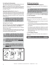
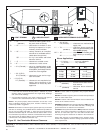
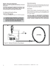
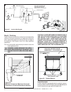
Figure 37. Junction Box Diagram
BLOWER
SENSOR
SWITCH
“FAN”
RECEPTACLE
SPEED
CONTROL
NOTE: IF ANY OF THE ORIGINAL WIRE
AS SUPPLIED WITH THE APPLIANCE
MUST BE REPLACED, IT MUST BE
REPLACED WITH TYPE 105 C RATED WIRE.
O
JUNCTION BOX
VARIABLE SPEED CONTROL
TEMPERATURE
SENSOR SWITCH
WHT
GRN
BLK
BLK
110-120 VAC
BLOWER
BLOWER RECEPTACLE
BLK
BLK
BLK
BLK
WHT
GROUND
WHT
BLK
BLK
BLK