


Heat & Glo • SL-350TRS-C, SL-550/750TRS-IPI-D • 2065-985 Rev. J • 5/06
38
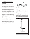
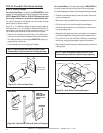
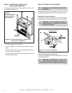
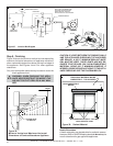
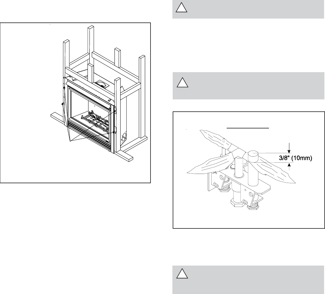
Step 4. Positioning, Leveling, and
Securing the Appliance
• Place the appliance into position.
• Level the appliance from side to side and from front to
back.
• Shim the appliance with non-combustible material, such
as sheet metal, as necessary.
• Secure the appliance to the framing using nails or screws
through the nailing tabs.
!
!
The diagram below shows how to properly position, level,
and secure the appliance.
Figure 32. Proper Positioning, Leveling, and
Securing of a Appliance
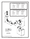
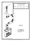
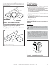
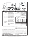
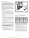
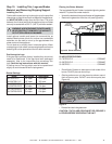
Figure 33. Gas Control Systems
STANDING PILOT
Step 5. The Gas Control Systems
WARNING: THIS UNIT IS NOT FOR USE WITH
SOLID FUEL.
The two types of gas control systems used with this model:
Standing Pilot Ignition and Intellifire Pilot Ignition (IPI).
Standing Pilot Ignition System
This system includes millivolt control valve, standing pilot,
thermopile/thermocouple flame sensor, and piezo ignitor.
WARNING: 110-120 VAC MUST NEVER BE
CONNECTED TO A CONTROL VALVE IN A
MILLIVOLT SYSTEM.
WARNING:
To ensure proper clearances
the front framing header
must be installed on its
narrow edge and to the
front of the frame.
NAILING TABS
(BOTH SIDES)
!
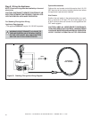
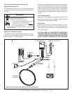
WARNING: CONTINUOUS 110-120 VAC
SERVICE MUST BE WIRED DIRECTLY TO
THE APPLIANCE JUNCTION BOX IN A IPI SYSTEM.
Intellifire Pilot Ignition (IPI) System
This system includes a 3V control valve, electronic module
and intermittent pilot.