


Heat & Glo • SL-350TRS-C, SL-550/750TRS-IPI-D • 2065-985 Rev. J • 5/06
19
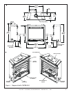
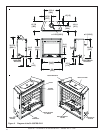
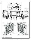
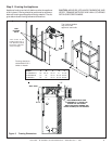
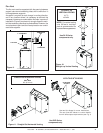
Figure 5. Framing Dimensions
Framing should be
constructed of 2 X 4
lumber or heavier.
The framing headers
may rest on the
appliance stand-offs.
Step 2. Framing the Appliance
Appliance framing can be built before or after the appliance
is set in place. Framing should be positioned to accommo-
date wall coverings and appliance facing material. The dia-
gram below shows framing reference dimensions.
CAUTION: MEASURE APPLIANCE DIMENSIONS AND
VERIFY FRAMING METHODS AND WALL COVERING
DETAILS BEFORE FRAMING.
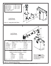
VENT
FRAMING
HOLE
E
D
Models A B C D E
SL-750TRS-IPI-D 42” 38 1/4” 16 1/4” 41” 27 7/8”
SL-550TRS-IPI-D 37” 33” 16 1/4” 36 1/2” 24 3/8”
SL-350TRS-C 34” 31” 16 1/4” 35 1/2” 22 3/8”
A
B
C
WALL STUD
NON-COMBUSTIBLE ZONE
IS DEFINED BY 3” ABOVE THE
ELBOW FOR THE ENTIRE
WIDTH AND DEPTH (BEHIND THE
FRONT HEADER) OF THE FIREBOX.
3”
2-1/4”
*The center of the
framing hole is one (1)
inch (25.4mm) above
the center of the hori-
zontal vent pipe.
*