


Heat & Glo • SL-350TRS-C, SL-550/750TRS-IPI-D • 2065-985 Rev. J • 5/06
40
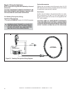
Step 8. Wiring the Appliance
NOTE: Electrical wiring must be installed by a licensed
electrician.
CAUTION: DISCONNECT REMOTE CONTROLS IF AB-
SENT FOR EXTENDED TIME PERIODS. THIS WILL PRE-
VENT ACCIDENTAL APPLIANCE OPERATION.
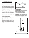
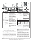
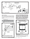
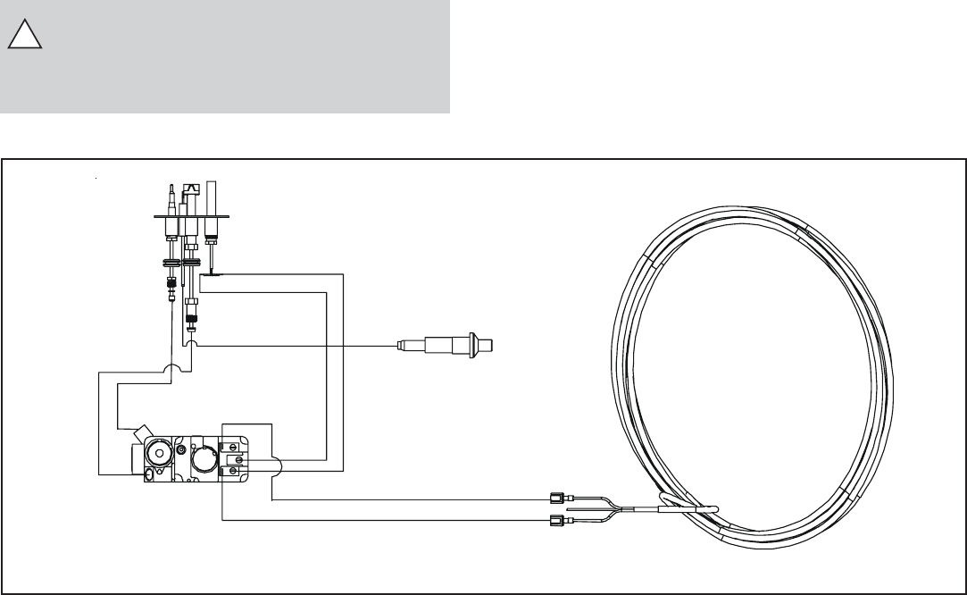
Figure 35. Standing Pilot Ignition Wiring Diagram
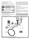
Optional Accessories
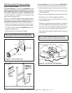
Optional fan and remote control kits require that 110-120
VAC be wired to the factory installed junction box before
the appliance is permanently installed.
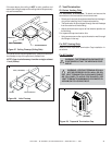
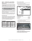
Wall Switch
Position the wall switch in the desired position on a wall.
Run a maximum of 25 feet (7.8 m) or less length of 18
A.W.G. minimum wire and connect it to the appliance ON/
OFF switch pigtails.
CAUTION: LABEL ALL WIRES PRIOR TO DISCONNEC-
TION WHEN SERVICING CONTROLS. WIRING ERRORS
CAN CAUSE IMPROPER AND DANGEROUS OPERATION.
VERIFY PROPER OPERATION AFTER SERVICING.
THERMOSTAT
WIRE ASSEMBLY
PIEZO
WHITE
RED
VALVE
PILOT
THERMOCOUPLE
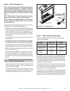
For Standing Pilot Ignition Wiring
Appliance Requirements
• This appliance DOES NOT require 110-120 VAC to operate.
!
WARNING: DO NOT CONNECT 110-120 VAC TO
THE GAS CONTROL VALVE OR WALL SWITCH
OR THE APPLIANCE WILL MALFUNCTION
AND THE VALVE WILL BE DESTROYED.