


27Heat & Glo • Cosmo-I30, Cosmo-I35 • 2239-900 Rev. H • 1/11
PLUG
120V EXISTING
OUTLET
GRN (2)
BLK (2)
BLK (2)
GRN (2)
BLK (2)
STEPS
3 & 4
WHT (2)
BLOWER
SPEED CONTROL
(RHEOSTAT)
SENSOR SWITCH
STEPS
1 & 2
STEP 5
BLOWERS
BLOWER
RECEPTICLE
BLK
GRN
BLK
BLK
GRN
BLK
WHT
GRN
BLK
BLK
GRN
WHT
BLK
BLK
PLUG INTO 120V
EXISTING OUTLET
DC REGULATOR
RECEPTICLE
AUX 300 MODULE
FAN
TO CONTROL
MODULE
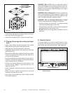
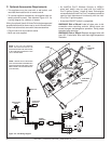
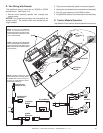
D. Fan Wiring with Remote
This appliance may be used with an RC200 or RC300
remote control. See Figure 10.3.
1. Remove cord assembly spades from rheostat and
sensor switch.
NOTICE: Fan speed and operation are controlled by the
remote control. The sensor switch and rheostat are no
longer needed.
2. Plug two cord assembly spade connectors together.
3. Unplug fan cord assembly from standard cord assembly.
4. Plug fan cord assembly into AUX300 module.
5. Plug AUX300 module into the standard cord assembly.
NOTE: USE ZIP TIES TO RESTRAIN
THE LOOSE WIRES UNDERNEATH
THE APPLIANCE AND KEEP THEM
AWAY FROM THE BLOWER WHEEL
(FAN BLADES).
NOTE: IF ANY OF THE ORIGINAL
WIRE AS SUPPLIED WITH THE
APPLIANCE MUST BE REPLACED,
IT MUST BE REPLACED WITH TYPE
105
0
C RATED WIRE.
E. Control Module Operation
See Section 2.H for control module operation instructions.
Figure 10.3 Wiring Diagram - Fan with RC200/RC300 Remote
NOTE: SENSOR SWITCH AND
RHEOSTAT SPEED CONTROL MUST
BE REMOVED FROM CIRCUIT IF
SYSTEM IS CONTROLLED WITH
RC200/RC300 REMOTE.