


Heat & Glo • Cosmo-I30, Cosmo-I35 • 2239-900 Rev. H • 1/11 26
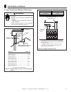
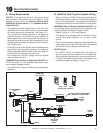
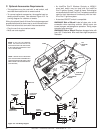
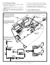
Figure 10.2 Fan Wiring Diagram
BLOWERS
BLOWER
RECEPTACLE
BLK
GRN
BLK
BLK
GRN
BLK
WHT
GRN
BLK
BLK
GRN
WHT
BLK
BLK
BLK
BLK
PLUG INTO 120V
EXISTING OUTLET
TEMPERATURE
SENSOR SWITCH
VARIABLE SPEED
CONTROL
DC REGULATOR
RECEPTACLE
JUMPER WIRE
PLUG
120V EXISTING
OUTLET
GRN (2)
BLK (2)
BLK (2)
GRN (2)
BLK (2)
RED
BLK
BRN
TO VALVE
TO VALVE BRACKET
(GROUND)
WHT (2)
GRN
ORG
BLOWER
SPEED CONTROL
(RHEOSTAT)
TEMPERATURE
SENSOR SWITCH
BLK
C. Optional Accessories Requirements
• This appliance may be used with a wall switch, wall
mounted thermostat and/or a remote control.
• To connect optional accessories, the supplied cord as-
sembly should be used. See attached Figure 10.2 for
a wiring diagram for a blower or remote.
Wiring for optional Hearth & Home Technologies approved
accessories should be done now to avoid reconstruction.
Follow instructions that come with those accessories.
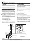
• Plug the cord into a convenient outlet.
• Must use cord supplied.
NOTE: USE ZIP TIES TO RESTRAIN
THE LOOSE WIRES UNDERNEATH
THE APPLIANCE AND KEEP THEM
AWAY FROM THE BLOWER WHEEL
(FAN BLADES).
NOTE: IF ANY OF THE ORIGINAL
WIRE AS SUPPLIED WITH THE
APPLIANCE MUST BE REPLACED,
IT MUST BE REPLACED WITH TYPE
105
0
C RATED WIRE.
• An IntelliFire Plus™ Wireless Controls or WSK-21
wired wall switch may be used with the IntelliFire
Plus™ Ignition System. Hearth & Home Technologies
recommends that IntelliFire Plus™ wireless controls be
used for their features and functionality with the Intel-
liFire Plus™ ignition system.
• A standard ON/OFF switch is compatible.
WARNING! Risk of Shock! Label all wires prior to dis-
connection when servicing controls. Wiring errors can
cause improper and dangerous operation. Verify proper
operation after servicing.
WARNING! Risk of Shock! Replace damaged wire with
type 105° C rated wire. Wire must have high temperature
insulation.