


Heat & Glo • Cosmo-I30, Cosmo-I35 • 2239-900 Rev. H • 1/11 22
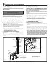
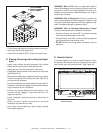
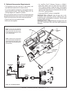
Figure 8.2
CUT AND BEND
FLASHING AS NEEDED
TO FIT CHIMNEY
SEALANT
ADHESIVE
• Trim chimney top plate to minimize excess overhang or
bend over fl ue tile (see Figure 8.2).
• Place 3/8 inch bead of 300º F silicone on fl ue tile top.
D. Placing, Securing and Leveling the Appli-
ance
• Install insert (without surround attached) into existing
fi replace while pulling collar slide plate forward.
• Install gas line into hole provided on insert side.
• If applicable install remote control wires into insert side
(see Section 8.E).
• Secure collar slide plate to appliance by placing locking
handle into position with locking tabs (see Figure 8.1)
and secure with #8 screw.
• Level the appliance from side to side and front to back. If
necessary, use the leveling legs included with the manual
bag to set each corner of the base.
• Position any excess fl exible vent pipe back up into
chimney without sagging. Twist and push flex vent
together to shorten.
• Install fiberglass insulation pieces to back face of
surround.
• Attach surround. Follow instructions for surround
installation included with the front.
• Push insert into the opening so that it tightly overlaps
the fi replace opening.
WARNING! Risk of Fire! Only an approved Hearth &
Home Technologies surround may be used to cover inte-
gral grills on solid fuel burning fi replaces. No other com-
ponents such as shrouds, sheetmetal plates, etc., may be
used to seal off vents.
WARNING! Risk of Explosion! Failure to position the
parts in accordance with these diagrams or failure to use
only parts specifi cally approved with this appliance may
result in property damage or personal injury.
WARNING! Risk of Explosion/Combustion Fumes!
Connect vent sections per installation instructions.
• Connect exhaust vent pipe ONLY to exhaust starting
collar and termination cap center collar.
• Connect inlet air vent ONLY to inlet air collar on appliance
and the termination cap inlet air collar.
• DO NOT allow vent to sag below connection point to
appliance.
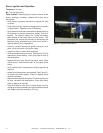
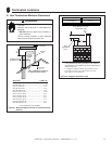
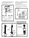
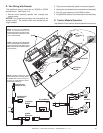
E. Remote Control
If a remote control kit is used to control blower function,
the Auxiliary 300 module can only be placed in the control
cavity to the right of the control panel. See Figure 8.3.
Figure 8.3 Location of AUX300 for Remote Control
Blower Function
AUXILIARY 300 MODULE