


17Heat & Glo • Cosmo-I30, Cosmo-I35 • 2239-900 Rev. H • 1/11
5
5
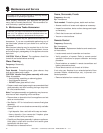
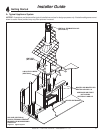
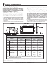
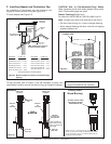
Fireplace Size Requirements
Figure 5.1 Fireplace Opening
In addition to these dimensions, also reference Clearances and Mantel Projections (Section 5.B).
E
D
C
I
B
A
G
H
F
MINIMUM FIREPLACE SIZE
Location
COSMO-I35 COSMO-I30
Inches Millimeters Inches Millimeters
A Rear Width 23-1/2 597 20-1/4 514
B Front Width 34-5/8 879 30-1/2 775
C Glass Opening Width 31-9/16 802 27-7/16 697
D Glass Opening Height 15-11/16 398 12-13/16 325
E Height-Front 24 610 20-1/2 521
F Height-Rear 21-1/16 535 17-5/8 448
G** Unit Depth 16 406 14-3/4 375
H Venting Depth 10-1/2 267 9-1/2 241
I
Height to Top of
Glass Frame
22 559 18-1/4 464
* Note: If exhaust collar on insert and fi replace damper do not line up, add 4 inches (102 mm) to minimum
fi replace height for bends in vent pipe.
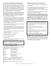
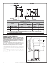
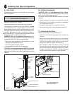
A. Minimum Fireplace Opening
Minimum fi replace opening requirements for a standard 3/4
inch deep surround are shown in Figure 5.1. For smaller
openings, an optional 1-1/2 inch deep surround is available
and dimensions are shown in Figure 5.2.
WARNING! Risk of Fire or Burns! Provide adequate
clearance around air openings and for service access.
Due to high temperatures, the appliance should be locat-
ed out of traffi c and away from furniture and draperies.
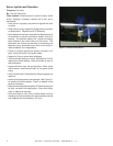
• The fi rebrick (refractory), glass doors, screen rails, screen
mesh and log grates can be removed from a factory
built fi rebox in order to gain minimum gas insert opening
requirements.
• Any smoke shelves, shields and baffl es may be removed
from the factory built fi rebox if attached with mechanical
fasteners.
• The metal fl oor of the solid fuel fi rebox may be removed to
facilitate the installation of the insert. The appliance may
not be placed directly on the base of the outer wrap, a 1/4
inch airspace must be provided between the insert and
the fl oor of the outer wrap. Use the levelling legs to raise
the insert a minimum of 1/4 inch. The original fi replace
may never be returned to solid fuel in this condition.
The sidewalls and top structure of the fi rebox may not
be altered with the exception of removable baffl es and
dampers.
• Cutting of any sheet metal parts of the fi replace in which
the gas fi replace insert is to be installed is prohibited,
except the fl oor as tested for and as noted above.
TOP VIEW FRONT VIEW
**Unit depth is measured to the back of the surround to give the depth needed for installation.
SIDE VIEW