


13
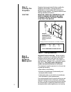
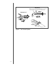
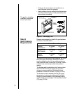
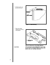
At the gas line access hole, use insulation to re-
pack the space around the gas pipe.
Insert insulation from the outside of the fireplace and
pack the insulation tightly to totally seal between the
pipe and the outer casing.
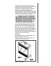
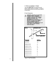
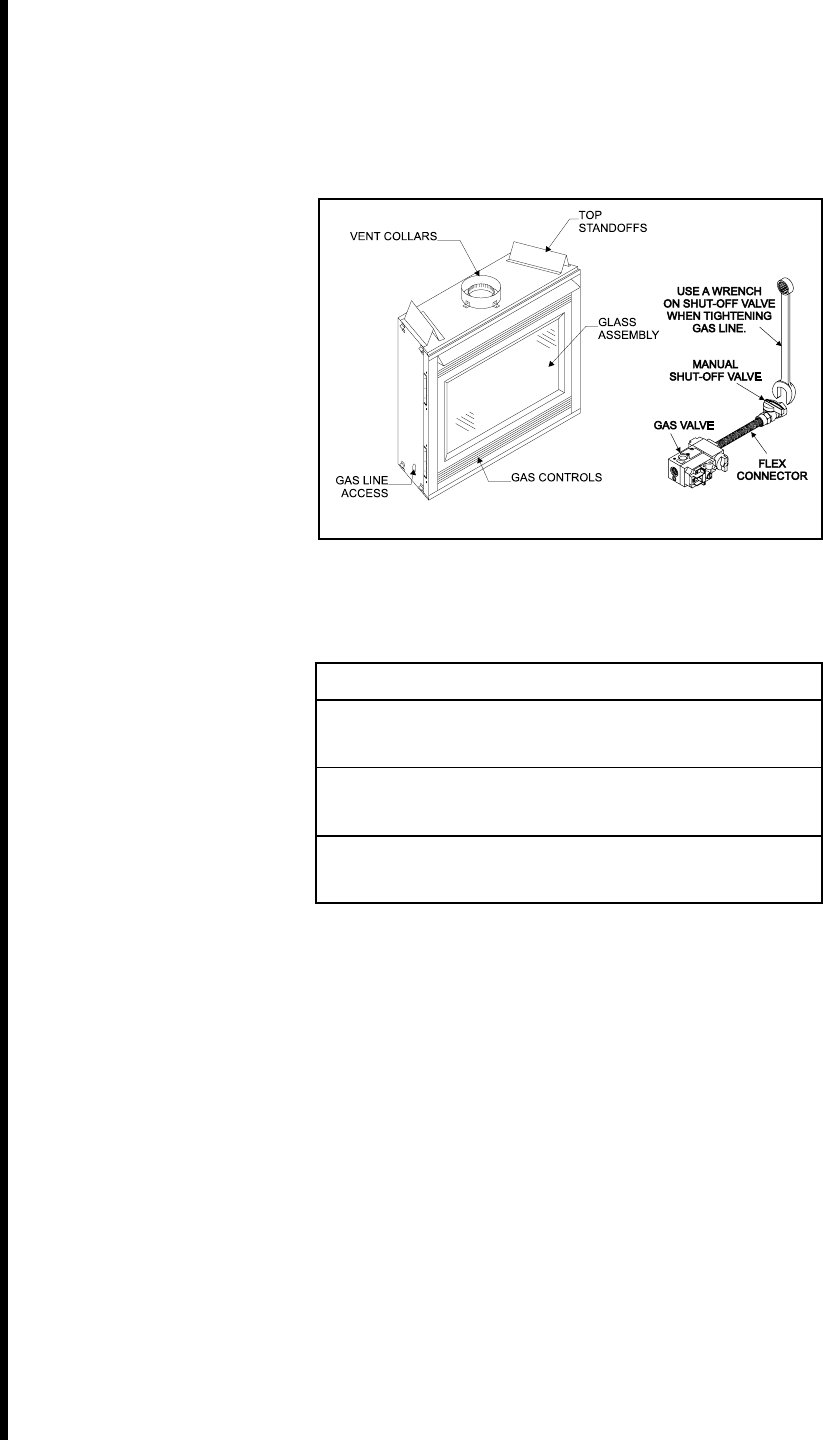
The gas line should be
installed by a qualified
service technician.
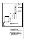
Figure 9. Gas Supply Line
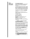
Step 8
Gas Pressure
Requirements
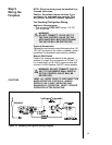
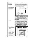
Pressure requirements for Heat-N-Glo gas fireplaces
are shown in the table below.
Pressure Natural Gas Propane
Minimum 5.0 inches 11.0 inches
Inlet Pressure w.c. w.c.
Maximum Inlet 14.0 inches 14.0 inches
Gas Pressure w.c. w.c.
Manifold 3.5 inches 10.0 inches
Pressure w.c. w.c.
The tap for the manifold and inlet pressures are on the
face of the gas control valve. Remove the control
panel covering the valve. Use a small screwdriver to
crack open the screw in the center of the tap. Position
a rubber hose over the tap to obtain the pressure
reading.
The fireplace and its individual shut-off valve must be
disconnected from the gas supply piping system
during any pressure testing of the system at test
pressures in excess of one-half (1/2) psig (3.5 kPa).
The fireplace must be isolated from the gas supply
piping system by closing its individual shut-off valve
during any pressure testing of the gas supply piping
system at test pressures equal to or less than one-half
(1/2) psig (3.5 kPa).