


7
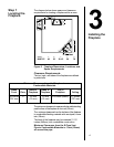
Step 4
Installing the
Vent System
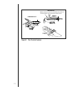
A. Vent System Approvals
Model 8000TVC is approved to use 6-inch (152mm)
diameter B-type vent. B-type vent must be used
when the vent system is within combustible
construction.
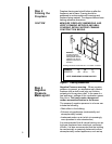
These models may also use single wall rigid or flexible
gas vent IF and ONLY IF the vent system is installed
within non-combustible construction such as a masonry
chimney. The same diameter noted above for B-type
vent must be used for single-wall vent. See Figure 5.
For B-type vent the clearance to combustibles is
1-inch. Follow vent manufacturers REQUIRED
clearances.
The flame and ember appearance may vary
based on the type of fuel burned and the venting
configuration used.
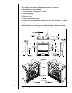
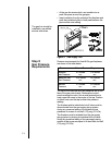
B. System Components.
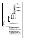
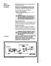
Vent System Configuration
RISE TO RUN RATIO = 2:1
MAXIMUM TOTAL HORIZONTAL RUN = 15 FT.
MINIMUM TOTAL VERTICAL RISE = 9 FT.
MAXIMUM NO. Of ELBOWS: 2 - 90
o
or 4 - 45
o
Plan and install the vent system using the parameters
shown above.
WARNING: YOU MUST NOT EXCEED
THESE PARAMETERS.
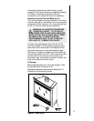
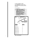
Connect a B-Type vent component to the flue outlet collar.
Look at the vent pipe through the holes in the 10 5/8
ring to check that the vent pipe is attached.
NOTE: It is always better to first attach a straight
section of
vent to the unit before attaching an elbow.
Avoid using elbows in the vent system if possible.
A 90-degree elbow can be attached directly to the unit.
If it is, it can be followed by a MAXIMUM 15-feet
horizontal run, a second 90-degree elbow ending in a
minimum 30 foot vertical.
A minimum of 9 foot vertical rise ending in a listed
termination cap is required for the unit.
Continue to add vent components, until the vent run is
completed.
WARNING: YOU MUST NOT EXCEED A
TOTAL MAXIMUM HORIZONTAL RUN
OF 15 FEET FOR THE ENTIRE VENT
SYSTEM.