


10
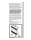
Step 5
Positioning,
Leveling, and
Securing the
Fireplace.
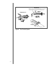
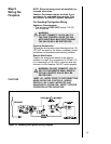
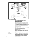
Standing Pilot Ignition System
This system includes millivolt control valve, standing
pilot, thermopile/thermocouple flame sensor, and
piezo ignitor.
WARNING
110-120 VAC MUST NEVER BE
CONNECTED TO A CONTROL VALVE
IN A MILLIVOLT SYSTEM.
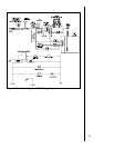
Direct Spark Ignition (DSI) System
The DSI system includes a 120V control valve,
electronic module, and spark ignitor/flame sensor.
WARNING
CONTINUOUS 110-120 VAC SERVICE
MUST BE WIRED TO THE FIREPLACE
JUNCTION BOX IN A DSI SYSTEM.
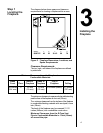
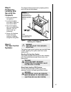
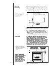
The diagram below shows how to properly position,
level, and secure the fireplace.
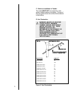
1. Place the fireplace
into position.
2. Level the fireplace
from side to side and
from front to back.
3. Shim the fireplace
with non-combustible
material, such as
sheet metal, as
necessary.
4. Secure the fireplace
to the framing by
nailing or screwing
using the nailing tabs.
Figure 7. Proper Positioning, Leveling, and
Securing of a Fireplace
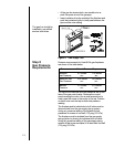
Step 6
The Gas Control
Systems
WARNING
THIS UNIT IS NOT FOR USE WITH
SOLID FUEL.
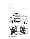
Two types of gas control systems are used with these
models: Standing Pilot Ignition and Direct Spark
Ignition (DSI).
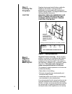
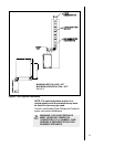
WARNING:
To ensure proper
clearances the front
framing header must be
installed on its narrow
edge and to the front of
the frame.
NOTE:
Non-combustible material
that is supplied with unit is
not shown for clarity.