


33
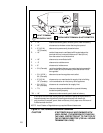
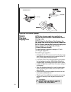
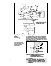
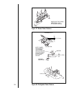
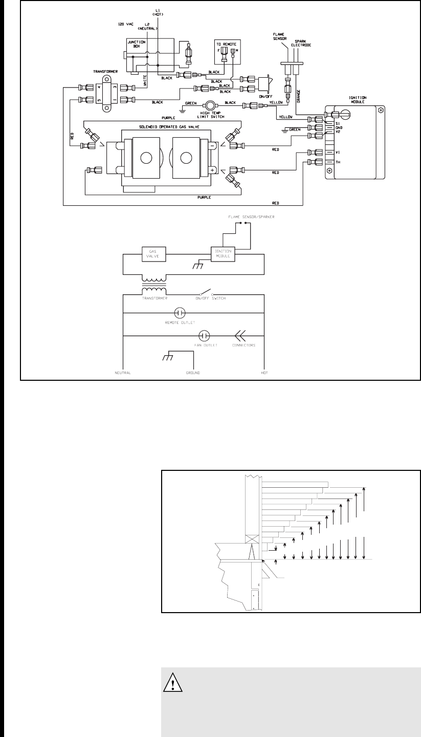
Figure 32. Direct Spark Ignition (DSI) Wiring Diagram
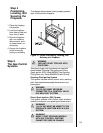
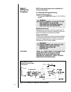
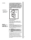
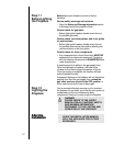
Step 9
Finishing
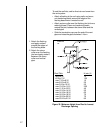
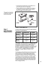
The following diagram shows the minimum vertical
and corresponding maximum horizontal dimensions
of fireplace mantels or other combustible projections
above the top front edge of the fireplace. See Figure 5
for other fireplace clearances.
Only non-combustible
materials may be used
to cover the black
fireplace front.
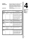
Figure 33. Minimum Vertical and Maximum
Horizontal Dimensions of
Combustibles above Fireplace
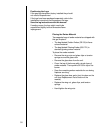
WARNING
WHEN FINISHING THE FIREPLACE,
NEVER OBSTRUCT OR MODIFY THE
AIR INLET/OUTLET GRILLES IN ANY
MANNER.
1.5"
3"
3.5"
4"
4.5"
5"
6"
7"
8"
9"
10"
11"
1"
2"
3"
4"
5"
12"
11"
10"
9"
8"
7"
6"
TOP FRONT EDGE
OF FIREPLACE
TOP FRONT EDGE
OF FIREPLACE
NOTE: ALL DIMENSIONS SHOWN
IN INCHES.
NOTE: ALL DIMENSIONS SHOWN
IN INCHES.
NOTE: MODELS SL-42DVT &
6000ARCH DO NOT HAVE A
HI-TEMP. LIMIT SWITCH.