


26
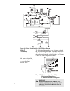
NOTE: IF ANY OF THE ORIGINAL WIRE
AS SUPPLIED WITH THE APPLIANCE
MUST BE REPLACED, IT MUST BE
REPLACED WITH TYPE 105 DEGREE C
RATED WIRE.
NOTE: IF ANY OF THE ORIGINAL WIRE
AS SUPPLIED WITH THE APPLIANCE
MUST BE REPLACED, IT MUST BE
REPLACED WITH TYPE 105 DEGREE C
RATED WIRE.
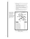
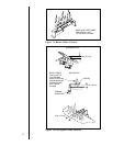
BLOWER
BLOWER RECEPTACLE
JUNCTION BOX
VARIABLE SPEED CONTROL
TEMPERATURE
SENSOR SWITCH
TEMPERATURE
SENSOR SWITCH
GROUND
WHT
BLK
BLK
GRN
WHT
BLK
BLK
BLK
BLK
BLK
BLK
BLK
110-120 VAC
BLK
WHT
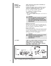
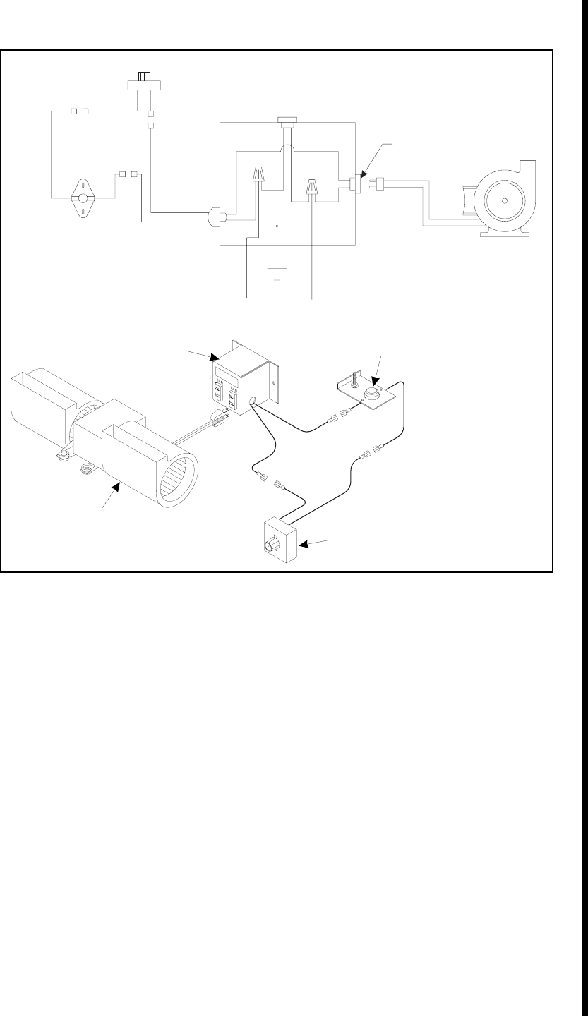
FAN WIRING DIAGRAM
Figure 25. Fan Wiring Diagram
For Direct Spark Ignition (DSI) Wiring
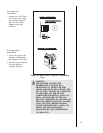
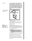
Appliance Requirements
This appliance requires that 110-120 VAC be wired to
the factory installed junction box. Maintain correct
polarity when wiring the junction box.
Optional Accessories
Optional fan and remote control kits require that 110-
120 VAC be wired to the fireplace junction box.
Remote Wall Switch
Position the remote wall switch in the desired position
on a wall. Run a maximum of 25 feet
(7.8 m) or less of 16 A.W.G. minimum wire and
connect it to the fireplace ON/OFF switch pigtails.
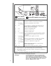
NOTE
Electrical wiring must be installed by a licensed
electrician.
CAUTION
LABEL ALL WIRES PRIOR TO DISCONNECTION
WHEN SERVICING CONTROLS. WIRING
ERRORS CAN CAUSE IMPROPER AND
DANGEROUS OPERATION. VERIFY PROPER
OPERATION AFTER SERVICING.
TEMPERATURE
SENSOR SWITCH
JUNCTION
BOX
FAN
SPEED CONTROL
(RHEOSTAT)