


23
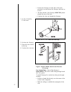
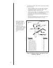
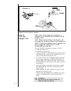
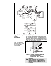
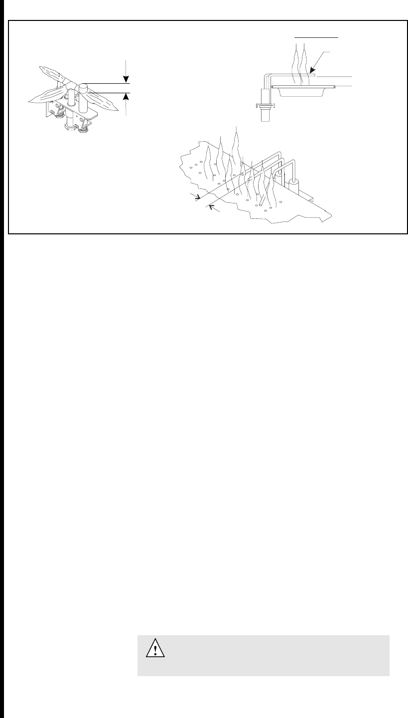
Figure 22. Gas Controls Systems
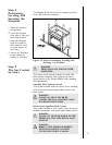
Step 6
The Gas
Supply Line
NOTE: Have the gas supply line installed by a
qualified service technician in accordance with all
building codes.
NOTE: Before the first firing of the fireplace, the
gas supply line should be purged of any trapped air.
NOTE: Consult local building codes to properly size
the gas supply line leading to the 1/2 inch
(13 mm) hook-up at the unit.
This gas fireplace is designed to accept a 1/2 inch
(13 mm) gas supply line.
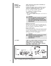
To install the gas supply line:
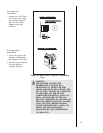
A listed 1/2 inch (13 mm) manual shut-off valve and a
listed flexible gas connector are connected to the 1/2
inch (13 mm) inlet of the control valve.
A 1/8 inch (3 mm) N.P.T. plugged tapping, accessible
for test gauge connection, should be provided for in
the gas supply line leading to the units shut-off valve.
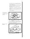
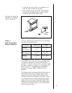
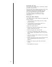
Locate the gas line access hole in the outer casing of
the fireplace.
Open the fireplace lower grille, insert the gas supply
line through the gas line hole, and connect it to the
shut-off valve.
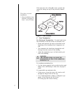
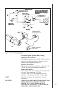
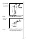
When attaching the pipe, support the control so that
the lines are not bent or torn.
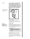
After the gas line installation is complete, use a soap
solution to carefully check all gas connections for
leaks.
WARNING
DO NOT USE AN OPEN FLAME TO
CHECK FOR GAS LEAKS.
3/16" (5 mm)
DSI IGNITION
IGNITOR
1/2" (13 mm)1/2" (13 mm
)
STANDING PILOT
3/8" (10 mm)