


The Quality Leader in Conditioning Air
Residential Split - 60Hz R410A
Rev.: 03 August, 2012
www.heatcontroller.com
25
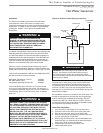
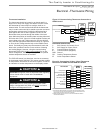
Thermostat Installation
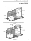
The thermostat should be located on an interior wall in a
larger room, away from supply duct drafts. DO NOT locate
the thermostat in areas subject to sunlight, drafts or on
external walls. The wire access hole behind the thermostat
may in certain cases need to be sealed to prevent erroneous
temperature measurement. Position the thermostat back
plate against the wall so that it appears level and so the
thermostat wires protrude through the middle of the back
plate. Mark the position of the back plate mounting holes and
drill holes with a 3/16” (5mm) bit. Install supplied anchors and
secure plate to the wall. Thermostat wire must be 18 AWG
wire. Wire the appropriate thermostat as shown in Figure 24
or 25 to the low voltage terminal strip on the DXM2 control
board. Practically any heat pump thermostat will work with
these units, provided it has the correct number of heating
and cooling stages. However, using the communicating
thermostat (7602-443) is highly recommended for on-site,
easier confi guration, monitoring and diagnosis. An optional
outdoor temperature sensor is available.
The 7602-452 sensor is a thermistor, used as an accessory
for thermostat model 7602-443. This sensor provides outdoor
air temperature information for the control system, as well as
an indication of outdoor temperature on the display screen.
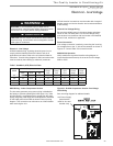
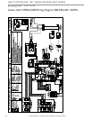
Thermostat
Compressor
Compressor Stage 2
Reversing Valve
Fan
24Vac Hot
24Vac Common
Fault LED
DXM2
Board
Y1
Y2
W
H
O
G
R
C
AL1
Y1
Y2
W
DH
O
G
R
C
L
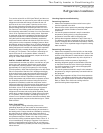
Dehumidification
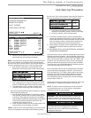
Notes:
Auxiliary Heat
1) ECM automatic dehumidification mode operates with dehumidification airflows
in the cooling mode when the dehumidification output from thermostat is active.
Normal heating and cooling airflows are not affected.
2) DXM2 board DIP switch S2-7 must be in the auto dehumidification mode for
automatic dehumidification
Non-AXM
Air Handler
Y1
Y2
W
H
O
G
R
C
AL1
Figure 25: Conventional 3 Heat / 2 Cool Thermostat
Connection to DXM2 and Non-AXM Air Handler
CAUTION!
CAUTION! Refrigerant pressure activated water regulating
valves should never be used with ClimateMaster
equipment.
Electrical - Thermostat Wiring
CAUTION!
CAUTION! Either a communicating thermostat (7602-
443) or confi guration tool (7602-444) MUST be used to
confi gure and diagnose this unit.
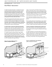
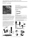
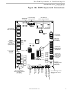
Thermostat Connections
C 24V Common for Control Circuit
R 24V Supply for Control Circuit
A+ Communications (Positive)
B – Communications (Negative)
GND Ground
OD Outdoor Temperature Sensor
ID Indoor Temperature Sensor
ATC32U** Thermostat
Unit with
AXM
Control
24Vac Hot
DXM2
Control
24V
Comm +
A+
A+
Comm -
B-
B-
OD
ID
GND
Outdoor
Sensor
(Optional)
Remote Indoor
Sensor
(Optional)
24Vac Common
Gnd
R
C
24V
A+
B-
Gnd
7602-443
WDG
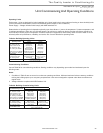
Figure 24: Communicating Thermostat Connection to
DXM2 Control