


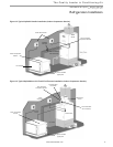
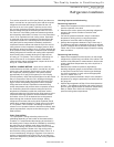
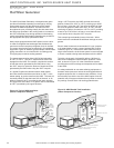

Line Set Installation
Figures 12a through 13b illustrate typical installations with
the “indoor” and “outdoor” versions of the compressor section
matched to either an air handler (fan coil) or add-on furnace
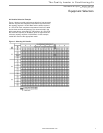
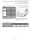
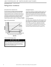
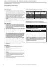
coil. Table 4 shows typical line-set diameters at various
lengths. Lineset lengths should be kept to a minimum and
should always be installed with care to avoid kinking. Line
sets over 60 feet [18 meters] long are not recommended due
to potential oil transport problems and excessive pressure
drop. If the line set is kinked or distorted, and it cannot be
formed back into its original shape, the damaged portion of
the line should be replaced. A restricted line set will effect the
performance of the system.
A reversible heat pump fi lter drier is installed on the liquid
line inside the compressor section cabinet (R-22 units only).
R-410A models are shipped with a fi lter drier (loose) inside
the cabinet that must be installed in the liquid line at the
line set. All brazing should be performed using nitrogen
circulating at 2-3 psi [13.8-20.7 kPa] to prevent oxidation
inside the tubing. All linesets should be insulated with a
minimum of 1/2” [13mm] thick closed cell insulation. All
insulation tubing should be sealed using a UV resistant
paint or covering to prevent deterioration from sunlight.
When passing refrigerant lines through a wall, seal
opening with silicon-based caulk. Avoid direct contact
with water pipes, duct work, fl oor joists, wall studs,
fl oors or other structural components that could transmit
compressor vibration. Do not suspend refrigerant tubing
from joists with rigid straps. Do not attach line set to the
wall. When necessary, use hanger straps with isolation
sleeves to minimize tranmission of line set vibration to the
structure.
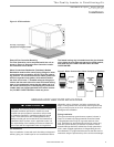
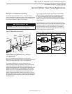
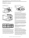
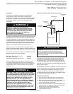
Installing the Lineset at the Compressor Section
Braze the line set to the service valve stubs as shown
in Figure 10. On installations with long line sets, copper
adapters may be needed to connect the larger diameter
tube to the stubs. Nitrogen should be circulated through
the system at 2-3 psi [13.8-20.7 kPa] to prevent oxidation
contamination. Use a low silver phos-copper braze alloy on
all brazed connections. Compressor section is shipped with
a factory charge. Therefore, service valves should not be
opened until the line set has been leak tested, purged and
evacuated. See “Charging the System.”
The Quality Leader in Conditioning Air
Residential Split - 60Hz R410A
Rev.: 03 August, 2012
www.heatcontroller.com
15
Refrigeration Installation
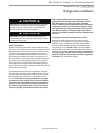
CAUTION! Installation of a factory supplied liquid line
bi-directional fi lter drier is required. Never install a suction
line fi lter in the liquid line.
CAUTION!
CAUTION! R-410A systems operate at higher pressures
than R-22 systems. Be certain that service equipment
(gauges, tools, etc.) is rated for R-410A. Some R-22
service equipment may not be acceptable.
CAUTION!