


HEAT CONTROLLER, INC. WATER-SOURCE HEAT PUMPS
Residential Split - 60Hz R410A
Rev.: 03 August, 2012
Heat Controller, Inc. Water-Source Heating and Cooling Systems24
Comp
Relay
24Vdc
EH1
EH2
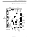
P6
Off On
JW3
c
1
a
y
c
2
a
y
CO
RV
RV
LT1
LT1
LT2
LT2
LP
LP
HP
P7
Status
Fault
CC
CCG
CO
S1
S2
12
1
4
Off On
AO2
P11
Gnd
T1
P10
T2 T2 T3 T3 T4 T4
T5
P9
T5
T6 T6
A0-1 A0-2
Off On
S3
RV
Relay
CCH
Relay
1 2 3 4
1 2 3 4 5 6 7 8
1 2 3 4 5 6 7 8
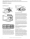
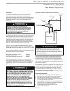
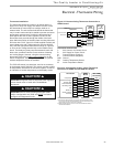
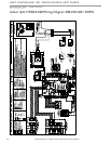
Figure 23: LT1 Limit Setting
DXM2 PCB
JW3-LT1
jumper should
be clipped
for low
temperature
(antifreeze)
operation
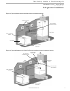
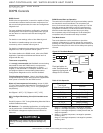
Low Voltage Field Wiring
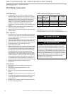
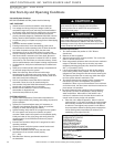
Accessory Connections
A terminal paralleling the compressor contactor coil has been
provided on the DXM2 control. Terminal “A” is designed to
control accessory devices. Note: This terminal should be used
only with 24 Volt signals and not line voltage. Terminal “A” is
energized with the compressor contactor.
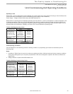
Figure 22: HTS Low Voltage Field Wiring
Low Water Temperature Cutout Selection
The DXM2 control allows the fi eld selection of low water (or
water-antifreeze solution) temperature limit by clipping jumper
JW3, which changes the sensing temperature associated
with thermistor LT1. Note that the LT1 thermistor is located
on the refrigerant line between the coaxial heat exchanger
and expansion device (TXV). Therefore, LT1 is sensing
refrigerant temperature, not water temperature, which is
a better indication of how water fl ow rate/temperature is
affecting the refrigeration circuit.
The factory setting for LT1 is for systems using water (30°F
[-1.1°C] refrigerant temperature). In low water temperature
(extended range) applications with antifreeze (most ground
loops), jumper JW3 should be clipped as shown in Figure
23 to change the setting to 10°F [-12.2°C] refrigerant
temperature, a more suitable temperature when using
an antifreeze solution. All residential units include water/
refrigerant circuit insulation to prevent internal condensation,
which is required when operating with entering water
temperatures below 59°F [15°C].
Electrical - Low Voltage
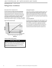
Figure 23a: Accessory Wiring
24VAC
DXM2
P2
C
A
Terminal Strip
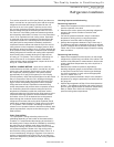
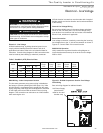
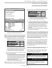
Motorized Modulating Water Control Valve - Open Loop
Ground Water Systems Only
An external valve should be used on ground water systems
to shut off fl ow when the compressor is not operating. Valve
kit AMMV4D is available for use with HTS024-048, and kit
AMMV5E is used with HTS060. See Figure 23b or the unit
wiring diagram for valve wiring detail. Further details on valve
operation are described later in this manual.
Figure 23b: Motorized Modulating Water Control Valve -
Open Loop Ground Water Systems Only
DXM 2
P11
P3
For MWV option, place jumper on 0-10V pins.
Ensure actuator direction switch is set as shown.