


HEAT CONTROLLER, INC. WATER-SOURCE HEAT PUMPS
Residential Split - 60Hz R410A
Rev.: 03 August, 2012
Heat Controller, Inc. Water-Source Heating and Cooling Systems22
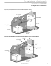
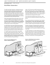
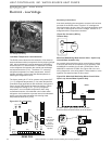
HWG Water Piping
1. Using at least 1/2” [12.7mm] I.D. copper, route and
install the water piping and valves as shown in Figures
15 or 16. Install an approved anti-scald valve if the 150°F
HWG setpoint is or will be selected. An appropriate
method must be employed to purge air from the HWG
piping. This may be accomplished by fl ushing water
through the HWG (as in Figures 15 and 16) or by
installing an air vent at the high point of the HWG piping
system.
2. Insulate all HWG water piping with no less than 3/8”
[10mm] wall closed cell insulation.
3. Open both shut off valves and make sure the tank drain
valve is closed.
Water Tank Refi ll
1. Close valve #4. Ensure that the HWG valves (valves #2
and #3) are open. Open the cold water supply (valve #1)
to fi ll the tank through the HWG piping. This will purge air
from the HWG piping.
2. Open a hot water faucet to vent air from the system until
water fl ows from faucet; turn off faucet. Open valve #4.
3.
Depress the hot water tank pressure relief valve handle to
ensure that there is no air remaining in the tank.
4. Inspect all work for leaks.
5.
Before restoring power or fuel supply to the water heater,
adjust the temperature setting on the tank thermostat(s)
to insure maximum utilization of the heat available from
the refrigeration system and conserve the most energy.
On tanks with both upper and lower elements and
thermostats, the lower element should be turned down
to 100°F [38°C] or the lowest setting; the upper element
should be adjusted to 120-130°F [49-54°C]. Depending
upon the specifi c needs of the customer, you may want
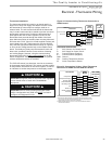
to adjust the upper element differently. On tanks with a
single thermostat, a preheat tank should be used (Fig 16).
6. Replace access cover(s) and restore power or
fuel supply.
Initial Start-Up
1. Make sure all valves in the HWG water circuit are
fully open.
2. Turn on the heat pump and allow it to run for
10-15 minutes.
3. Set S3-4 to the “ON” position (enabled) to engage the
HWG.
4. The HWG pump should not run if the compressor is not
running.
5. The temperature difference between the water entering
and leaving the HWG coil should be approximately
5-10°F [3-6°C].
6. Allow the unit to operate for 20 to 30 minutes to insure
that it is functioning properly.
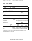
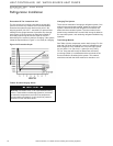
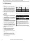
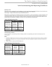
Table 6: HWG Water Piping Sizes and Length
Unit
Nominal
Tonnage
Nominal
HWG Flow
(gpm)
1/2" Copper
(max length*)
3/4" Copper
(max length*)
2.0 0.8 50 -
3.0 1.2 50 -
4.0 1.6 45 50
5.0 2.0 25 50
*Maximum length is equivalent length (in feet) one way of type L
copper.
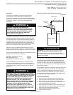
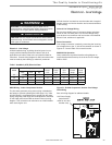
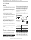
Hot Water Generator
WARNING!
WARNING! The HWG module is an appliance that operates
in conjunction with the heat pump system, the hot water
system and the electrical system. Installation should only be
performed by skilled technicians with appropriate training
and experience. The installation must be in compliance with
local codes and ordinances. Local plumbing and electrical
building codes take precedence over instructions contained
herein. The Manufacturer accepts no liability for equipment
damaged and/or personal injury arising from improper
installation of the HWG module.
CAUTION!
CAUTION! Locate Refrigerant lines to avoid accidental
damage by lawnmowers or children.
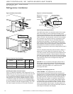
NOTICE! Make sure the compressor discharge line is
connected to the “Hot Gas In” stub on the Heat Recovery Unit.