


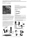
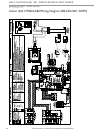

HWG Wiring - Indoor Compressor Section
The hot water generator pump power wiring is disabled at
the factory to prevent operating the HWG pump “dry.” After
all HWG piping is completed and air purged from the water
piping, the pump power wires should be applied to terminals
on the HWG power block PB2 as shown in the unit wiring
diagram. This connection can also serve as a HWG disable
when servicing the unit.
The Quality Leader in Conditioning Air
Residential Split - 60Hz R410A
Rev.: 03 August, 2012
www.heatcontroller.com
23
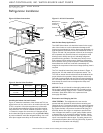
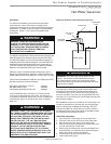
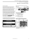
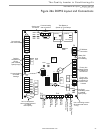
Figure 21: R-410A Compressor Section Line Voltage
Field Wiring
Electrical - Line Voltage
Electrical - Line Voltage
All fi eld installed wiring, including electrical ground, must
comply with the National Electrical Code as well as all
applicable local codes. Refer to the unit electrical data for
fuse sizes. Consult wiring diagram for fi eld connections that
must be made by the installing (or electrical) contractor.
All fi nal electrical connections must be made with a length of
fl exible conduit to minimize vibration and sound transmission
to the building.
General Line Voltage Wiring
Be sure the available power is the same voltage and phase
shown on the unit serial plate. Line and low voltage wiring
must be done in accordance with local codes or the National
Electric Code, whichever is applicable.
Power Connection
Line voltage connection is made by connecting the incoming
line voltage wires to the “L” side of the contactor as shown in
Figures 21. Consult Table 7for correct fuse size.
208-230 Volt Operation
Verify transformer tap with air handler wiring diagram to
insure that the transformer tap is set to the correct voltage,
208V or 230V.
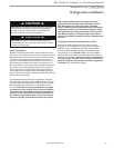
WARNING!
CAUTION!
WARNING! To avoid possible injury or death due to
electrical shock, open the power supply disconnect switch
and secure it in an open position during installation.
CAUTION! Use only copper conductors for fi eld installed
electrical wiring. Unit terminals are not designed to accept
other types of conductors.
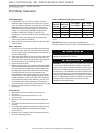
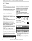
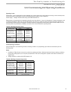
Table 7: GeoMax 2 (HTS) Electrical Data
Model
Compressor
HWG
Pump
FLA
External
Pump
FLA
Total
Unit
FLA
Min
Circuit
Amps
Max
Fuse/
HACR
RLA LRA Qty
024 10.7 56.0 1 0.4 4.0 15.1 17.8 25
036 17.0 87.0 1 0.4 4.0 21.4 25.7 40
048 21.5 100.0 1 0.4 4.0 25.9 31.3 50
060 26.0 125.0 1 0.4 4.0 30.4 36.9 60
See unit wiring diagram for addtional details.
Unit Power Supply
(see electrical
table for wire and
breaker size)