


Heat Controller, Inc. HBH/V SERIES Engineering Design Guide
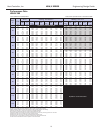
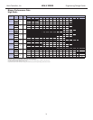
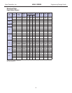
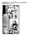
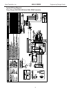
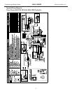
HB - Vertical Upow
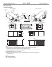
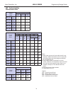
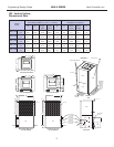
Dimensional Data
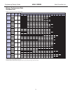
Notes:
1. While clear access to all removable panels is not
required, installer should take care to comply with
all building codes and allow adequate clearance
for future eld service.
2. Front & Side access is preferred for service
access. However, all components may be serviced
from the front access panel if side access is not
available. (Except on TCV 009-030 with front
return)
3. Discharge ange is eld installed.
4. Condensate is 3/4” IPT.
Legend:
CAP = Control Access Panel
BSP = Blower Service Panel
CSP = Compressor Access Panel
ASP = Alternative Service Panel
Vertical
upow
Model
Overall Cabinet
A
Width
B
Depth
C
Height
006 - 012
in
cm
19.1
48.5
19.1
48.5
22.0
55.9
015 - 018
in
cm
21.5
54.6
21.5
54.6
39.0
99.1
024 - 030
in
cm
21.5
54.6
21.5
54.6
40.0
101.6
036 - 042
in
cm
21.5
54.6
26.0
66.0
45.0
114.3
048 - 060
in
cm
24.0
61.0
32.5
82.6
46.0
116.8
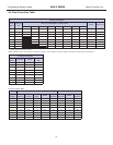
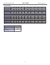
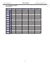
Vertical
Upow
Model
Water Connections - Standard Units
1 2 3
Loop
In
D
Loop
In
E
Loop
Out
F
Loop
Out
G
Cond. 3/4” IPT
Loop
In/Out
IPT
H I
006 -
012
in
cm
1.4
3.6
1.6
4.1
9.5
24.1
1.6
4.3
6.1
15.6
1.6
4.1
1/2”
015
in
cm
1.9
4.8
1.4
3.6
13.8
35.1
1.4
3.6
8.1
20.6
1.4
3.6
1/2”
018
in
cm
1.9
4.8
1.4
3.6
12.9
32.8
1.4
3.6
8.1
20.6
1.4
3.6
1/2”
024
in
cm
1.9
4.8
1.4
3.6
13.8
35.1
1.4
3.6
8.1
20.6
1.4
3.6
3/4”
030
in
cm
1.9
4.8
1.4
3.6
15.2
38.6
1.4
3.6
8.1
20.6
1.4
3.6
3/4”
036
in
cm
1.9
4.8
1.4
3.6
15.7
39.9
1.4
3.6
8.1
20.6
1.4
3.6
3/4”
042
in
cm
1.9
4.8
1.4
3.6
16.6
42.0
1.4
3.6
8.1
20.6
1.4
3.6
3/4”
048
in
cm
1.9
4.8
1.4
3.6
16.6
42.2
1.4
3.6
8.1
20.6
1.4
3.6
1”
060
in
cm
1.9
4.8
1.4
3.6
17.2
43.7
1.4
3.6
8.1
20.6
1.4
3.6
1”
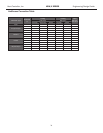
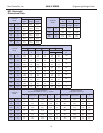
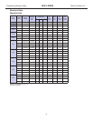
Vertical
Model
Electrical Knockouts
J
1/2”
K
1/2”
L
3/4”
Low
Voltage
Low
Voltage
Power
Supply
006 - 012
in
cm
2.9
7.3
5.9
14.9
8.9
22.5
015 - 060
in
cm
4.1
10.5
7.1
18.1
10.1
25.7
26