


HearthStone Quality Home Heating Products Inc Tucson Model #8700
19
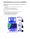
RESTRICTION PLATE
The restriction plate is used to control the
draft of the heater. Controlling the draft also
changes the aesthetics of the flame. The
restriction plate has eight settings, one (1)
being the lowest and eight (8) being the
highest. For a fast moving flame with lots of
action, use a low setting. For a slow, lazy
flame, a high setting should be used. See
Figure 11 for instructions on how to adjust
the restriction plate settings.
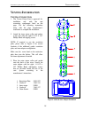
RESTRICTION PLATE POSITION
A vent restriction plate is available for the
appliance to adjust the flow rate of exhaust
gases. This insures proper flames for the
wide variety of vent configurations and
efficiency. The restriction plate consists of a
rotating shutter below the starter section of
pipe and an adjustment plate with index
holes used to hold the shutter in a fixed
position. Depending on the vent
configuration, you may be required to adjust
the restriction plate position. Refer to pages
21 – 22 for positioning of the restriction
plate.
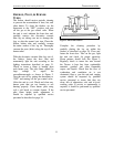
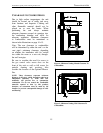
ADJUSTMENT TO RESTRICTION
PLATE
Remove the log set before adjusting
restriction plate by following the log set
removal on page 29. Make sure the unit is
cool before touching any part of the firebox
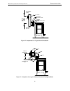
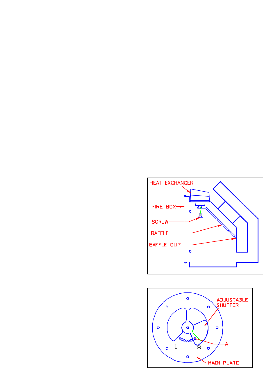
and log set. Remove the exhaust baffle by
removing the one screw in the center of the
baffle (refer to Figure 10). The baffle will
fall out once the screw is removed. Be
careful not to drop the baffle on the burner
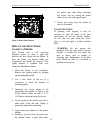
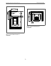
tube or burner tube holder. Once the baffle
is set aside, check the restriction plate screw
location. There are eight locations that the
restriction plate can be positioned. (refer to
Venting Configuration – Figures 14 – 16 for
recommended restriction plate positions)
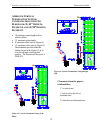
(refer to Figure 11 for proper adjustment
plate index location) ‘A’ in Figure 11 shows
the locating screw that determines the
position of the plate.
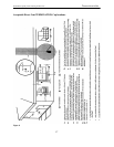
NOTE: These positions are based on lab
results and can have some variance.
Remove the screw and position the
restriction plate in the desired location.
Fasten the screw into the proper hole and
tighten. Reinstall the exhaust baffle by
setting the back edge of the baffle into the
baffle clip attached to the back wall of the
firebox. Then push the baffle against the
heat exchanger and reinstall the fasten bolt.
Reinstall the log set and ember strip as
described in the log set installation
procedure on page 28.
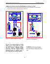
Figure 10: Baffle Removal
Figure 11 : Restriction Plate Adjustments