


Page 38
7036-135E
September 1, 2008
R
Mt. Vernon Pellet Insert (AE)
11
Reference Materials
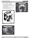
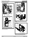
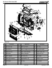
9. Firepot
The firepot is made of high quality ductile iron. The floor of
the firepot automatically opens for cleaning and is operated
by the auto-clean firepot system. The floor needs to return
to a completely closed position or the appliance will not
operate properly.
10. Fuses
There are three fuses. Two fuses are located on the inside
of the control board. One fuse is AC and operates the
igniter and the other fuse is DC and operates all of the
other components. The third fuse is located in the power
supply. A fuse will blow should a short occur and shut off
power to the appliance. The fuses can only be serviced by
an authorized dealer.
11. Heat Exchanger
The heat exchanger is located behind the baffle and it
transfers heat from the exhaust system into the convection
air chamber. Remove the cast iron baffle to access the heat
exchanger.
12. Hopper Lid Switch
The hopper lid switch is located on the right side inside the
hopper. It senses whether the hopper lid is open and displays
an icon on the wall control and will turn off the feed motor.
13. Igniter
The igniter is mounted on the base of the firepot. Combustion
air travels over the red hot igniter creating super heated air
that ignites the pellets.
14. Low Fuel Indicator
The low fuel indication is attached to the left side of the
hopper. It senses the amount of fuel in the hopper and will
display an icon on the wall control when the fuel level is
low.
15. Optical Switch (Auger)
The optical switch is located on top of the feed system and
communicates to the wall control that the auger is spinning
or it has stopped.
16. Power Receptacle
The power receptacle is located on the left side of the
appliance, behind the left cast side panel. Check the wall
receptacle for 120 volt, 60 Hz (standard current). Make sure
the outlet is grounded and has the correct polarity. A good
quality surge protector is highly recommended to protect
the electronics.
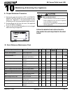
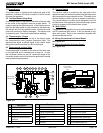
When describing the location of a component,
it is always AS YOU FACE THE FRONT OF
THE APPLIANCE.
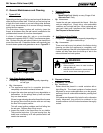
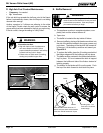
5. Convection Blower
The convection blower is mounted at the bottom left rear of
the appliance. The convection blower pushes heated air
through the heat exchange system into the room.
6. Door Switch
The door switch is mounted on the right side of the firebox
behind the door handle. It senses when the door is open
and will display an icon on the wall control, and will turn off
the auto-clean system and feed motor for safety.
7. Combustion (Exhaust) Blower
The combustion (exhaust) blower is mounted in the bottom
right rearof appliance. The blower is designed to pull the
exhaust from the appliance and push it out through the
venting system.
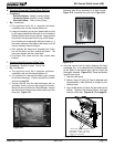
8. Feed System
The feed system is located on the right side of the appliance
and can be removed as an entire assembly. The assembly
includes the feed motor, mounting bracket, bearing and feed
spring (auger). The hollow feed spring (auger) pulls pellets
up the feed tube from the hopper area and drops them down
the feed chute into the firepot.
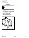
1. Auto-Clean Motor
The auto-clean motor is located under and behind the
firepot on the left side, inside the convection air chamber.
It automatically opens and closes the firepot floor so ashes
can fall into the ash pan.
2. Auto-Clean Switch
The auto-clean switch is located on top of the auto-clean
motor. It communicates to the control board when the firepot
floor is open and when the auto-clean system has completed
its cycle and is back in the home (closed) position.
3. 12 Volt Battery Back-Up Cable
This is an optional accessory. It will plug into the appliance
next to the power outlet located behind the left cast side
panel. An icon will display on the wall control when the
appliance has lost main power and is running on battery
back-up.
4. Control Board
The control board is located on the lower left side of appliance,
behind the left side panel and above the vacuum switch. It
controls the functioning of the appliance and communicates
with the wall control. The control board can only be opened
by an authorized dealer.
A. Component Functions