


R
September 1, 2008
7036-135E
Page 19
Mt. Vernon Pellet Insert (AE)
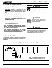
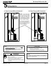
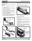
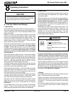
C. Hearth Support
Included in Kit: (1) bottom, (1) trim front, (2) trim sides, (2)
trim extensions
Tools Needed: Phillips head screw driver, measuring tape,
gloves
Figure 19.1
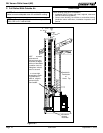
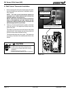
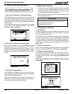
Figure 19.4 - Shown with Cast Panel Set
Basic
Cast
Attach Trim to Base
from underneath
Attach Trim to Insert from
inside Insert.
Install Front Trim Last,
Corner Overlap Side
Trim Pieces
5 in
3 in
5 inch
high Set
3 inch
high Set
Location of Latch
for Removing
Cast Sides
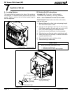
Lower the leveling
bolts if necessary to
keep the insert level
when installing the
Hearth Support.
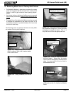
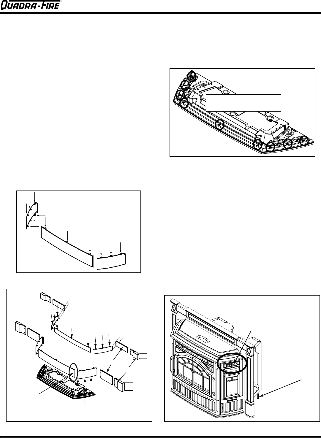
D. Removal of Cast Sides
You will need to remove the cast sides in order to install
the panel and trim set.
1. There is a latch on the back side of the cast side in the
middle of the top opening of the cast side as indicated
in Figure 19.4.
2. Place your fingers inside the opening and squeeze
the latch. The side can now be pulled toward you and
removed. Place on a protective surface so as not to
damage the finish.
3. To replace the side, set the bottom in first. Squeeze the
latch in an open position. Place the cast side into posi-
tion and then release the latch. The latch hooks onto a
bracket to hold the side in place.
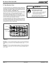
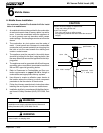
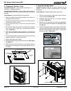
1.
Remove contents from box and lay on protective surface
to avoid scratching the paint.
2. Lay front and sides face down. Bend the tabs down
toward the inside. Figure 19.1.
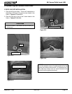
3.
The side pieces are shipped flat. It
is must easier to flex
the sides into a bowed position before installing.
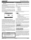
4.
Lay the cast bottom face up.
Attach the 2 sides FIRST and
then the front piece. Figure 19.2.
5. Turn the cast bottom right side up
and attach the panel
extensions. Note the alignment hole.
6. Attach the appropriate footers depending on the panels
& trim set you are installing. The footers come in 2 sizes,
3 and 5 inches. Discard the footers not used.
Bend tabs down. Shipped
flat from the factory.
Figure 19.2
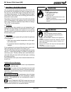
7. Place the assembled hearth support under the insert.
Lower the leveling bolts if necessary to keep the insert
level.
8. Open the door and attach the hearth support to the insert.
There are 9 attachment holes. Figure 19.3.
attachment holes - on
each side and in the front
Figure 19.3