


Page 20
7036-135E
September 1, 2008
R
Mt. Vernon Pellet Insert (AE)
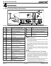
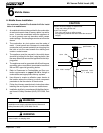
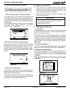
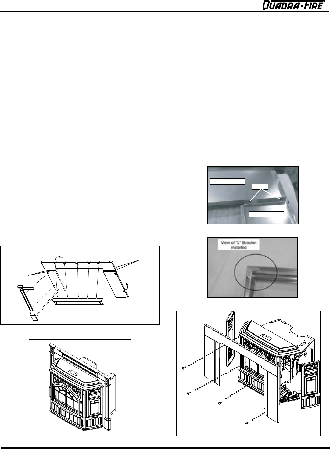
E. Panel and Trim Set - Cast
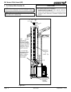
Figure 20.5
Figure 20.1
Figure 20.4
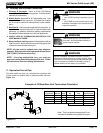
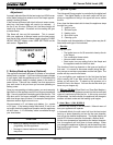
Figure 20.2- Completed View
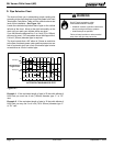
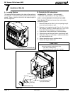
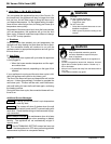
F. Panel & Trim Set, Basic
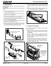
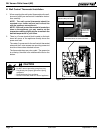
1. Secure the top panel to the panel sides with the
screws provided. Figure 20.3.
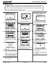
2. Assemble the trim with the (2) corner brackets
provided. Figure 20.4.
3. Remove the 2 cast sides and slide the assembled
trim over the assembled panel set.
See Figure 19.4
on page 19.
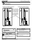
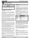
4. Carefully slide panel and trim over the top of the insert
into place matching the mounting holes on the panel
with the mounting holes on the insert. Secure with
screws provided. Figure 20.5.
Back of Top Panel
Back of Side Panel
Screws
Included in Panel & Trim Kit:
(2) corner brackets and set
screws; (1) trim set, 3 piece; (2) side panels; (1) top panel;
(4) screws.
Tools Needed: Powered Phillips head screw driver
Figure 20.3
Shown with trim installed on panel set
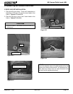
1. Screw panels
together
2. Bend tabs down
1. Screw panels
together
3. Install Cast Trim Header
2. Bend tabs
down
Included in Panel Kit: (2) side panels, left and right; (1)
panel top; (1) fastener package.
Included in Cast Trim Kit:
(2) cast trim legs, left and right; (1)
cast trim header; (2) cast trim footers, left and right; (1) fastener
package.
Tools Needed: Powered Phillips head screw driver
1.
Remove contents from box being careful not to scratch or
damage the cast trim pieces.
2. Lay the panel set face down on protective covering to prevent
scratching the painted surface.
3. Secure the panel legs to top panel with the screws
provided.
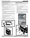
4. Now bend the tabs down toward the backside of the panel
set, 5 on top and 2 on each leg. Leave the panel set face
down. Figure 20.1.
5. Place the corresponding cast trim pieces ( 2 cast trim legs
and 1 cast trim header) underneath the panel set, also face
down.
6. Place washer provided over tab and secure the trim and panel
together with screw. Continue for all tabs.
7. Secure cast footers with screws.
8. Remove both left and right cast sides from insert.
See Figure
19.4 page 19.
9. Slide panel and trim over the top of the insert into place
matching the mounting tabs on the panel with the slots on
the insert.