


Page 18
7036-135E
September 1, 2008
R
Mt. Vernon Pellet Insert (AE)
7
Appliance Set-Up
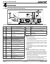
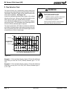
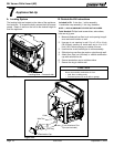
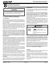
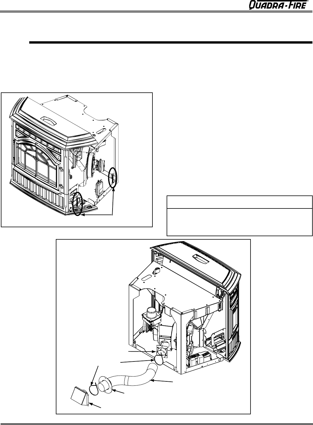
A. Leveling System
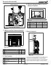
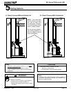
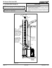
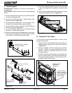
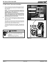
B. Outside Air Kit Instructions
Included in Kit: 2 wire ties, 1 collar assembly,
1 termination cap assembly, 1 trim ring, fasteners.
NOTE: 3 INCH ALUMINUM FLEX PIPE NOT INCLUDED.
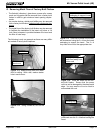
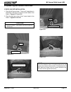
1. Measure distance from floor to air vent opening in appli-
ance and mark location on wall.
2. Use saw to cut opening in wall. Cut a 3-1/2 to 4 inch
(89-102mm) opening on inside wall and a 4 to 4-1/2
inch (102-114mm) opening on outside of house.
3. Use wire ties to secure flex pipe to collar assembly.
4. Slide trim ring over flex pipe and run pipe through wall.
5. Attach flex pipe (not included) to outside termination
cap with second wire tie.
6. Secure termination cap to outside surface.
7. Secure trim ring to interior wall.
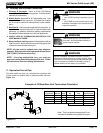
Tools Needed: Phillips head screw driver; wire cutters;
hole saw or jig saw.
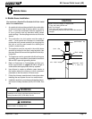
CAUTION
Never draw outside combustion air from:
• Wall, floor or ceiling cavity
• Enclosed space such as an attic or garage
The leveling bolts are located on the sides of the appliance,
front and rear. To access the bolts, remove the front access
panels. Reach in and turn the bolt to the desired height to
level the appliance.
Figure 18.1
Collar
Wire Ties
Trim Ring
Termination Cap
3 inch Aluminum Flex
Pipe (not included)
Figure 18.2
Leveling Bolts - 2 on each side