


20
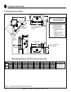
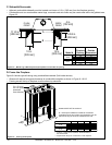
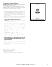
A
Fireplace
Opening
B
Outside
Dimensions
in.
36 41
mm
914 1041
in.
42 47
mm
1067 1194
Model #
EL36
EL42
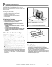
B
A
9 3/4 in.
[248 mm]
12 in.
[305 mm]
12 in.
[305 mm]
11 1/4 in.
[286 mm]
FLUSH
FRONT
4 in.
[102 mm]
BRICK
FRONT
50° angle
39° angle
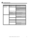
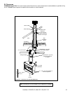
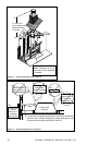
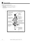
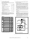
D. Frame the Fireplace
Figure 6.4 shows typical framing using combustible materials (2x4 lumber shown).
• Observe all required air space clearances to combustible materials as shown in Figure 6.1 & 6.2.
• Framing across the top of replace must be above top standoffs.
B
C
A
2 in. (51 mm)
min. air space
clearance
from chimney.
Header MUST NOT be notched!
D
D = extra space needed for outside air connection.
If outside air duct has no bend, this dimension may be
reduced as long as minimum clearances are met.
Model A B* C** D
in.
42 21 1/2 39 3/4 8
mm
1067 546 1010 203
in.
48 21 1/2 39 3/4 8
mm
1219 546 1010 203
* If interior of chase will be drywalled, add the thickness to
this measurement.
** Adjust header height for a raised floor under fireplace.
EL36
EL42
Figure 6.4 Framing the Fireplace
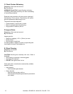
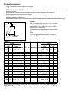
C. Sidewalls/Surrounds
• Adjacent combustible sidewalls must be located a minimum of 12 in. (305 mm) from the replace opening.
• Combustible and non-combustible mantel legs, surrounds and stub walls may be constructed within the gridded area,
Figure 6.3.
Figure 6.3 Mantel Leg or Wall Projections (Acceptable on both sides of opening)
Heatilator • EL36/EL42 • 4044-132 • Rev AD • 7/12