


Page 18
7014-083E
September 1, 2008
R
CB1200-I Pellet Insert
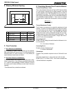
Left Corner
Piece
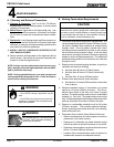
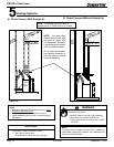
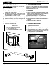
Rear Vent Installation Preparation:
1. Remove the ENTIRE exhaust blower housing by remov-
ing the 4 nuts using a 7/16 inch socket wrench. Set the
nuts aside for later use.
2. Remove the 4 screws and remove the vertical exhaust
transition pipe exhaust blower housing.
3. Remove any silicone sealant remaining on the blower
housing.
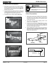
4. Attach the rear vent adapter to the exhaust blower hous-
ing with 4 screws. Figure 18.2.
5. Apply a bead of high temperature silicone adhesive
around the juncture of the blower housing and rear vent
adapter, smoothing it around the joint to ensure that a
good seal is made.
6. Re-install the exhaust blower housing (now with rear vent
adapter attached) with the 4 nuts previously removed in
Step 1.
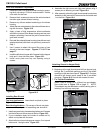
7. Use 2 screws to attach left corner filler piece of rear
shroud to the insert hopper. Figures 17.1 & 17.2 on
page 17.
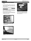
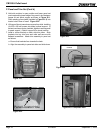
8. Install the left shroud corner with 2 screws into the hopper
body and 1 down into filler piece. Figure 18.1.
9. Install cover plate over top vent opening using 4
screws.
Figure 18.1
Figure 18.2
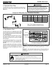
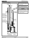
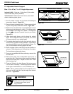
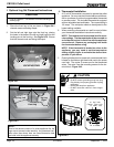
1. Install rear panel using 4 screws along bottom and 2 screws
into the left shroud corner piece at the top. Figure 18.3.
2. If your installation does not include an outside air kit,
attach cover plate with 4 screws.
3.
Attach left shroud panel using seven screws, 3 on top and
bottom and 1 along the side. Figure 18.3.
Top Vent Applications: Leave knock-out plate in place.
Figure 18.3
Rear Vent Applications: Clip corners of knock-out plate,
remove and discard, prior to assembling rear shroud kit.
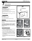
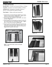
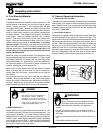
6. Beginning at the right shroud panel drill into hopper body
through the 3 pre-drilled openings and the 2 pre-drilled
openings on the rear shroud panel. Figure 18.5. Continue
around to left shroud corner panel at the 2 pre-drilled
openings. Figure 18.6. Secure with screws to insert.
7. For Top Vent Installation:
Install 3 inch or 4 inch (76 or 102mm) top vent adapter.
See circled area in Figure 17.3 on page 17. NOTE:
This adapter may be attached to outside venting prior to
latching it on to the top vent pipe.
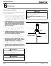
Attaching Shroud to Hopper Body:
Installing Rear Shroud
4.
Assemble the right corner and right panel pieces using 4
screws prior to attaching to insert. Figure 18.4.
5.
After assembly,
attach the right shroud panel/corner
piece
assembly to the insert with 3 screws across the bottom and
1 on the side. Figure 18.4.
Attach right
corner piece to
side panel first.
Right Corner Piece
Right Side
Rear Panel
Outside Air
Cover Plate
Knock-Out
Plate
Rear Panel
Left Side
rill oles
rill oles
Rear Panel
rill oles
Figure 18.5
Figure 18.3
Figure 18.4
Figure 18.6