


8
Clearance is the empty space required between
the stove or chimney connector and the nearest
combustible surface or object, such as walls, ceilings,
oors, or furniture. Clearance distances may only be
reduced by using methods approved by either the
CAN/CSA B365 standard (Canada) or NFPA 211 (U.S.)
Contact your building authority for information if you are
interested in reducing clearance distances below those
presented here.
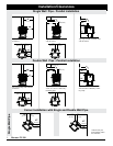
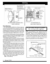
A parallel installation is one in which the back and
sides of the stove are parallel to the walls behind and
to the side of the stove. A corner installation is one in
which the back of the stove is positioned diagonally
across a corner of the room. Each installation requires
its own set of clearances.
For parallel installations, the required clearance
distances from the stove are:
1) to the side wall, 20" (508 mm);
2) to the back wall, 18" (458 mm).
3) From the chimney connector to the wall, 31"(787 mm)
4) Hortizontal pipe to the ceiling, 15"(381 mm).
: For a vertical chimney connector in a parallel
installation the distance from the connector to the side
wall must be 31"(787 mm), due to the required side
clearance of the stove itself. Fireplace installations must
meet these same clearance requirements; specically
follow these guidelines for mantel and trim clearances.
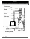
For corner installations, the clearance distances from
the stove are 18"(458 mm) from each corner of the stove
measured straight to the nearest combustible material,
and 27" (686 mm) from the chimney connector to the
walls.
From the front of the stove, clearance to combustible
materials such as furniture, curtains, fuel, etc.: 48"(1220
mm) in the . and 60"(1524 mm) in Due to
excessive heat build-up at the wall passthrough, using
double wall pipe, horizontal venting is only approved
into a masonry chimney.
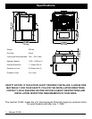
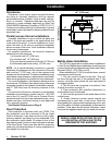
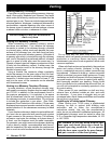
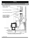
Floor protection is required under your TL300. This
oor protection must be a minimum of 20 ga. sheet
metal in thickness, it can also be stone or tile or other
masonry material, providing it is non-combustible. This
oor protection must extend 18 inches in front of the
door opening and 8 inches to each side and to the rear
of the stove body. There must also be oor protection
under any horizontal sections of venting regardless of
their height from the oor.
The TL300 is approved for mobile home installations
in the US only. Mobile Home installation should be done
in accordance with the Manufactured Home and Safety
Standard (HUD), CFR 3280, part 24.
When installing the TL300 in a mobile home, several
requirements must be met:
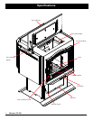
1. The unit must be bolted to the oor. This can
be done through the rear of the pedestal with 3" lag
screws, using the holes where the unit was bolted to
the shipping pallet.
2. The unit must be connected to outside air. See
Outside air section on page 21.
3. Floor protection and specied clearances to
combustibles must be followed.
4. Unit must be grounded to the metal frame of the
mobile home.
5. Smoke detectors and/or smoke alarms are
recommended on each oor of the house. Note that
when loading re, some smoke seepage may occur, and
set off the alarm. Ventilate as necessary to eliminate the
problem. If the alarm should sound otherwise, cease
the use of the appliance and call your dealer for service.