18
Wiring
Always disconnect the power cord before the unit
is pulled from the mounting frame.
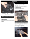
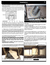
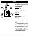
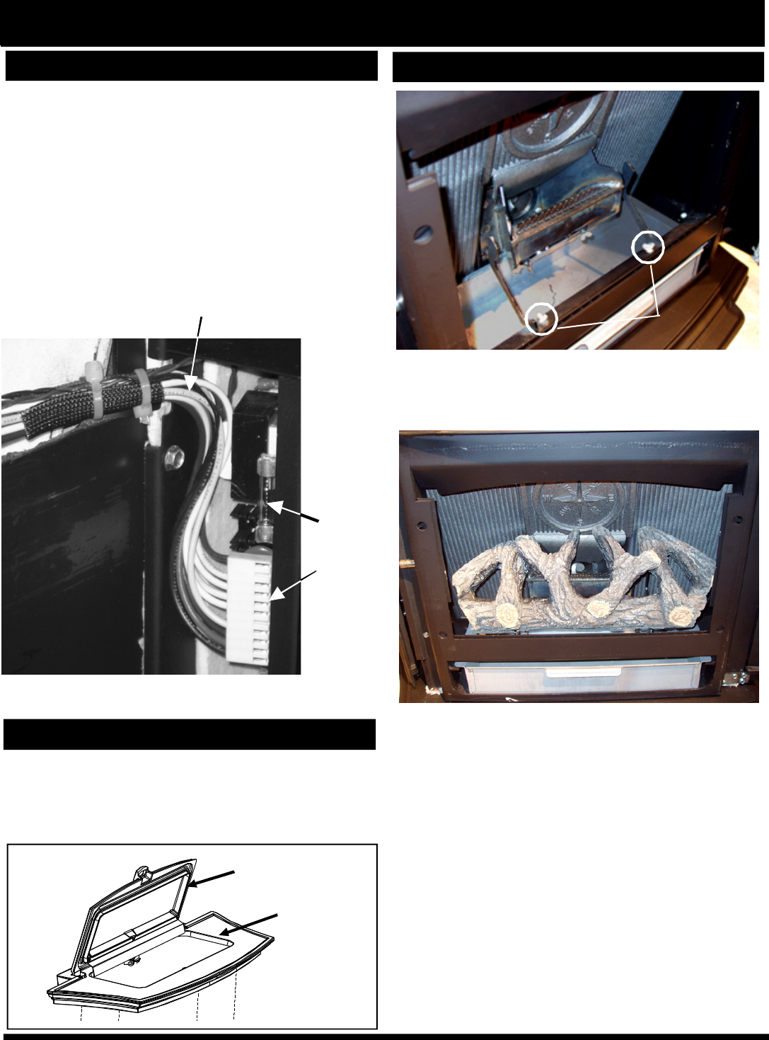
As you can see, the control board is easily accessible
from the rear with the body pulled out of the frame,
even if it is only pulled out several inches.
•
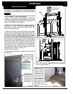
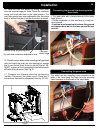
Always inspect the wiring harness of the 11 pin sock-
ets (large white flat plug where all of the power wires
terminate.)
•
Always inspect the wiring harness where the wires
transfer from the control to the rear inside of the body.
•
Make sure there are no worn or frayed areas.
Installation
Inspect the wiring harness transition area: This is the area
that comes closest to the mounting frame as the unit is slid
in and out of the frame.
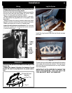
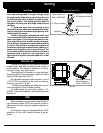
11 pin
socket
on rear
of control
board
6 amp
glass
fuse
Fig. 40
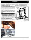
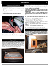
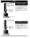
Hopper lid foam
gaskets
Cast Top
Fig. 41
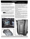
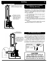
Log Set Option
Fig.42
Fig. 43
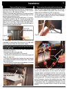
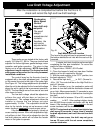
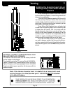
Install the log bracket with the two thumb screws
provided.
Center the log in the firebox opening with the bottom
front edge over the thumb screws. The log branch
tips only rest on the bracket arms for easy installa-
tion and removal.
IMPORTANT NOTE: BEFORE CLEANING THE
HEAT EXCHANGERS, THE LOG AND THE
LOG BRACKET MUST BE REMOVED.
REMINDERS
•
Do not allow pellets or sawdust to build up on the
hopper lip.
•
Inspect the hopper lid gasket for damage. A good
hopper lid seal is very important for proper opera-
tion.
Thumb
Screws
Evaluation notes were added to the output document. To get rid of these notes, please order your copy of ePrint IV now.


