


8
Tips On Installation
Before the positioning of the unit can be de-
cided a few questions should be considered?
1. Can the unit be vented properly and installed
safely?
2. Will exhaust be vented where fumes can build
up or be drawn into lower levels of the structure
3. Will fumes and y ash affect the exterior of the
structure or surrounding structures?
4. Are there any local regulations governing the
use and placement of the unit?
5. Are there any structural reasons why the unit
cannot be placed where you want?
6. How close is the electrical outlet?
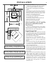
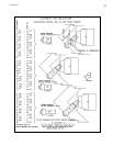
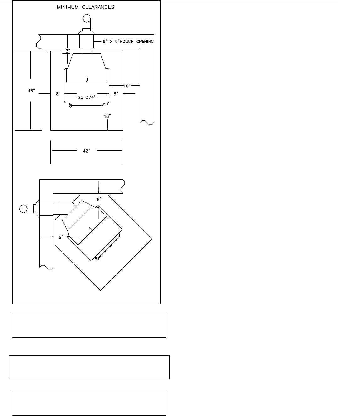
Follow the guidelines to the left regarding
clearances to combustible materials.
Floor Protector
This stove should be placed on a non-combus-
tible oor protector extending 16 inches to the front,
8 inches to the sides, and 1 inch to the rear.
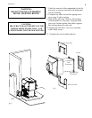
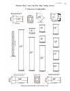
Straight Through Wall
1. When positioning of the unit has been decided,
use measurements on Page 10 for cutting the hole
through the wall. Don’t forget to gure the thick-
ness of the oor protector used.
2. Cut at least a 9" x 9" hole through the wall.
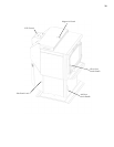
3. Remove the side doors / rear cover assembly
(6 black screws, 5/16" socket or straight screw-
driver)
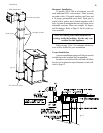
4. Place the unit in front of the hole approximately
1/2" closer to the wall than the length of the wall
termination. (From outside of wall to back of unit
where termination bolts up)
5. Take the wall termination outside and slide it into
the hole until it mates to the rear of the unit. Go
inside and install the bolts and tighten, making
sure the gasket is in place and the ue pipe sec-
tion is level.
6. Reposition the unit inward until the stainless steel
intake section comes against the outside wall
surface. NOTE: If the wall is over 8" thick you
will need a longer wall termination. The standard
termination will provide 3" of wall clearance
behind the stove, with a 8" wall. Therefore, with
a 5" thick wall, it will provide 6" of clearance
behind the stove.
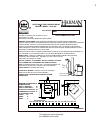
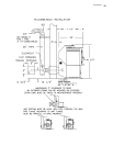
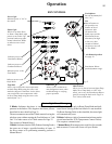
INSTALLATION
DO NOT INSTALL A FLUE DAMPER IN THE
EXHAUST VENTING SYSTEM OF THIS UNIT
DO NOT CONNECT THIS UNIT TO A CHIM-
NEY FLUE SERVING ANOTHER APPLIANCE.
INSTALL VENT AT CLEARANCES SPEC-
IFIED BY THE MANUFACTURER
g. 6
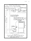
g. 7