


9INSTALLATION
Only For Qualified Installers
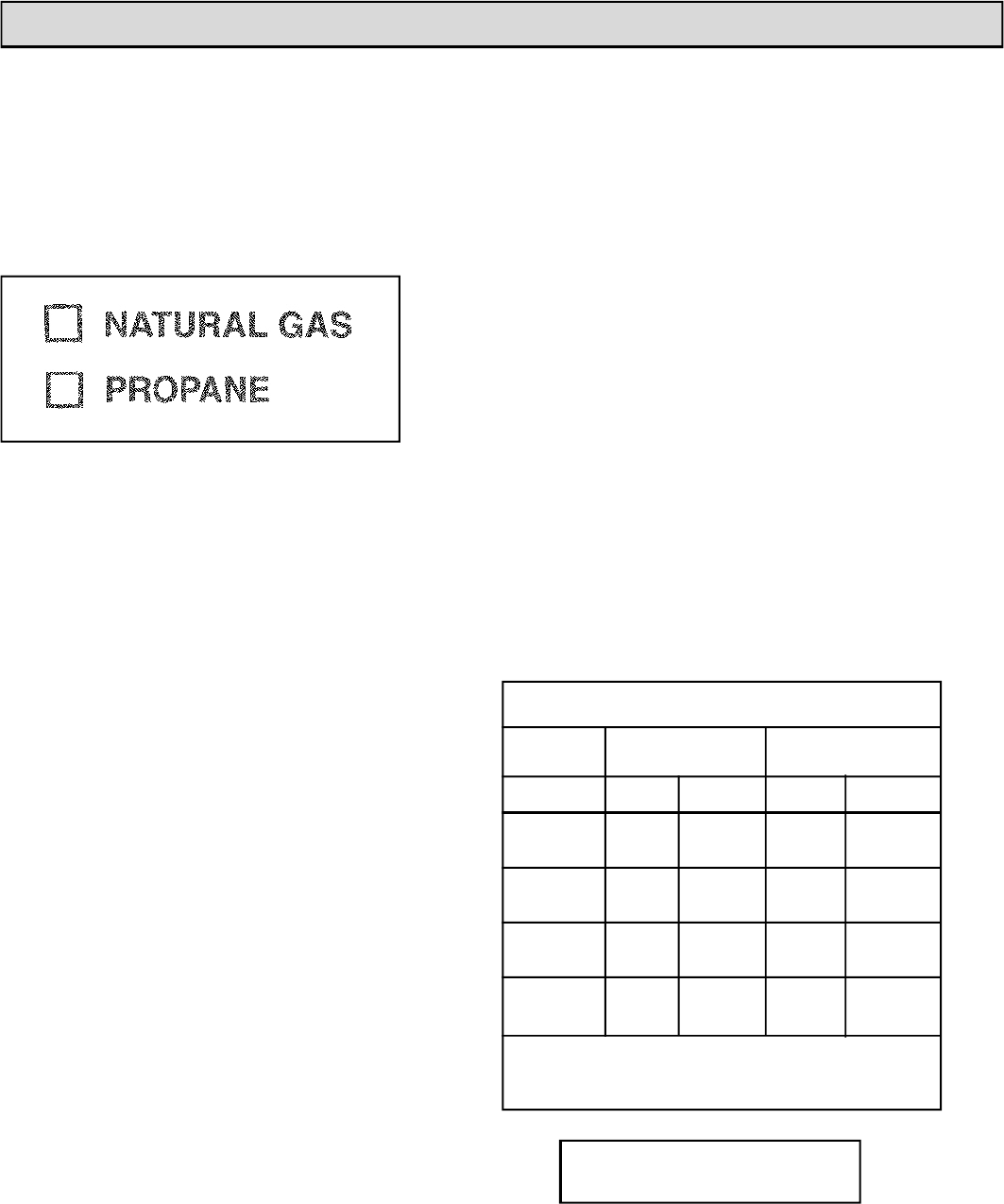
Burn Only the Fuel for which the Heater is
Equipped
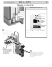
The Conquest can burn either natural gas or pro-
pane, but requires a change-over kit for natural gas.
The label on the burner system module indicates the
fuel for which it is equipped. A second label, (on the
valve) also indicates the fuel type.
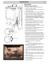
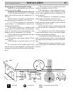
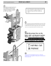
Making The Connection
The gas inlet is located on the bottom right side
of the stove. The inlet fitting is a 1/2" male flare
fitting.
A separate gas shut-off valve and a 1/8" N.P.T.
plugged tapping should be installed immediately up-
stream of the connection to the appliance.
The Conquest Direct Vent Gas Heater must be
disconnected from the gas supply piping during any
pressure testing of that system at pressures in excess
of 1/2 psig (3.5 kPa).
The Conquest gas control valve must be in the
OFF position during any pressure testing of the gas
supply system at pressures equal to or less than 1/2
psig (3.5 kPa).
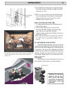
WARNING: To avoid pipe compounds from
entering into the gas train, apply compounds only
to male pipe threads and do not apply compound
to the first two threads.
CAUTION: TEST ALL JOINTS FOR LEAKS
BEFORE OPERATING.
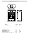
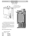
Gas Pressure Requirements:
Correct gas pressure and the use of a properly
sized gas supply line are essential for the safe and
efficient performance of this appliance. Make sure
that the plumber or gas supplier checks the gas sup-
ply line and gas pressure at installation.
NOTE: Improper gas pressure can affect heater
performance, flame color, or cause pilot outage.
Natural Gas:
Maximum inlet pressure 7.0" w.c. (1.74 kPa)
Minimum inlet pressure 5.0" w.c. (1.25 kPa)
Gas manifold pressure 3.8" w.c. (0.87 kPa)
LPG Gas:
Maximum inlet pressure 13" w.c. (3.24 kPa)
Minimum inlet pressure 11.5" w.c. (2.74 kPa)
Gas manifold pressure 11" w.c. (2.49 kPa)
DO NOT USE THIS HEATER IF ANY PART
HAS BEEN UNDER WATER OR EXPOSED TO
MOISTURE CORROSION. IMMEDIATELY
CALL A QUALlFlED SERVICE TECHNICIAN TO
INSPECT THE HEATER AND REPLACE ANY
PART OF THE CONTROL SYSTEM AND ANY
GAS CONTROL WHICH HAS BEEN UNDER
WATER.
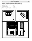
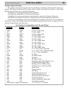
Pipe Length Schedule 40 Pipe Tubing, Type L
(Feet) Inside Diameter Outside Diameter
N.G. L.P. N.G. L.P.
0-10 1/2" 3/8" 1/2" 3/8"
1.3 cm 1.0 cm 1.3 cm 1.0 cm
10-40 1/2" 1/2" 5/8" 1/2"
1.3 cm 1.3 cm 1.6 cm 1.3 cm
40-100 1/2" 1/2" 3/4" 1/2"
1.3 cm 1.3 cm 1.6 cm 1.3 cm
100-150 3/4" 1/2" 7/8" 3/4"
2.0 cm 1.3 cm 2.3 cm 2.0 cm
RECOMMENDED GAS PIPE DIAMETER
NOTE: NEVER USE PLASTIC PIPE. CHECK TO
CONFIRM WHETHER YOUR LOCAL CODES ALLOW
COPPER TUBING OR GALVANIZED PIPE.
A LABEL ON THE BURNER SYSTEM
MODULE STATES THE FUEL FOR
WHICH THE HEATER IS EQUIPPED.
Evaluation notes were added to the output document. To get rid of these notes, please order your copy of ePrint IV now.