


19INSTALLATION (Options)
Only For Qualified Installers
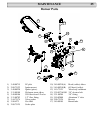
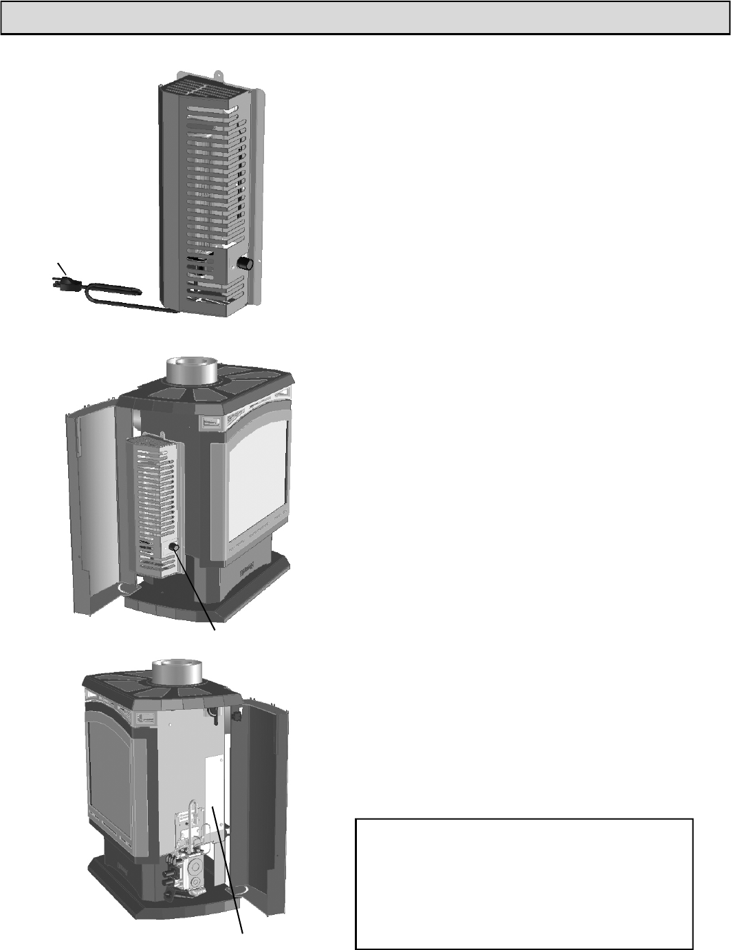
Optional Blower
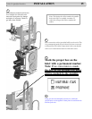
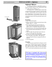
The Blower Kit (Part # 1-00-09102) includes a
blower assembly ready to bolt to the left side of the
stove and a blower chamber cover.
The blower has a variable speed control knob
to adjust the blower speed as desired. A special switch
is used to automatically start the blower when the
stove temperature is hot enough to blow warm air.
This switch will also stop the blower when the stove
temperature drops below the point that warm air is
available.
Installation
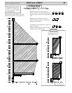
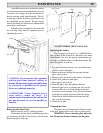
1. Open the left side panel.
2. Remove the four screws from the left side of the
firebox with a
5
/
16
” socket.
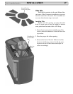
3. Place the blower as shown and start the top
screw. This will hold the blower in place and
make it easier to install the other three screws.
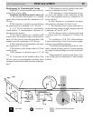
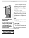
4. Route the power cord rearward between the side
panel and the pedestal and plug into a 120 volt
outlet.
5. Open the right side panel and remove the two
screws on the right side of the firebox.
6. Use the two screws to fasten the blower cham-
ber cover plate to the firebox. This plate pre-
vents air from the blower escaping from the air
chamber.
7. Close side panels.
Operation
Turn the speed control knob clockwise until it
clicks. This is the full speed position. Turning the
knob farther in the clockwise direction will gradu-
ally reduce the blower speed. To turn the blower
“OFF” turn the knob counterclockwise until it clicks.
Blower Assembly
Speed Control Knob
Blower Chamber Cover
Power Cord
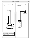
This blower is equipped with a three-prong
(grounding) plug for protection against shock
hazard and should be plugged directly into a
properly grounded three-prong receptacle.
Do not cut or remove the grounding prong
from the plug.
Evaluation notes were added to the output document. To get rid of these notes, please order your copy of ePrint IV now.