


Page 7SKU 92966
For technical questions, please call 1-800-444-3353.
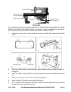
Power Switch
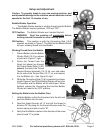
Mounting the Thread Stand
Note: The Thread Stand is designed to be mounted on the Table Stand Kit (Model
03929 - not included). Unless indicated otherwise, all parts referred to
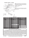
in this set of instructions are listed in the Bobbin Winder & Thread Stand
Unit Parts List found on page 23. During assembly, it will be helpful to
refer to that list and the diagram above it on the same page.
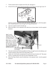
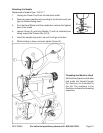
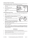
14. Locate the large hole in the far right corner (from the location that the operator will be
seated) of the Table (not included). Place the Rubber Washer (10-41) and Washer
(10-33) onto the Lower Spool Rest Rod (10-32) and insert the Rod into the hole mentioned
above. Place another Washer (10-33) over the end of the Rod, and thread on and tighten
a Nut (10-34).
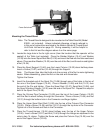
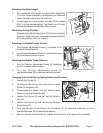
15. Place the Spool Support (10-42) over the Lower Column (10-32) about halfway down.
Insert a Screw (10-27) and Nut (10-43) through the Support.
Note: The Support has tabs that hold onto the corners of the Nut to make tightening
easier. When assembling, place the Nut on the side with these tabs.
Tighten the Screw.
16. Insert the threaded end of the Spool Pin (10-36) through one of the holes in the top of
the arm of the Spool Support (10-42). Place a Washer (10-28) and Nut (10-31) over
the end of the Pin and tighten. Place the Spool Rest (10-37), Spool Mat (10-38), and
the Spool Vibration Stopper (10-35) over the end of the Spool Pin. Repeat this step for
both of the Spool Pins (10-36).
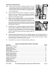
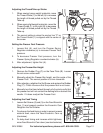
17. Place the Column Pipe Connector (10-29) over the top of the Lower Column (10-32)
until the Rod is about halfway through the Connector. Place a Screw (10-30) and Nut
(10-31) through the bottom hole in the Connector and finger-tighten.
18. Place the Upper Spool Rest Rod (10-26) into the top of the Column Pipe Connector
(10-29). Place a Screw (10-30) and Nut (10-31) through the top hole in the Connector.
Tighten all of the Screws and Nuts in the Connector.
19. Place the Thread Hanger (10-24) about halfway over the top of the Upper Column
(10-26). Insert a Screw (10-27) and Nut (10-43) through the Hanger as explained in the
note in step 14, above. Tighten the Screw and place the Column Cap (10-25) over the
end of the Upper Column (10-26).