


SKU 47821 For technical questions, please call 1-800-444-3353 Page 8
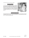
Providing a Power Source
1. Find a 110 VAC, fused, electrical box nearest the placement of the Control Box (B).
If none exists, a licensed electrician will have to run new cable (14 AWG) and conduit
from the electrical distribution box to the Control Box (B).
2. If an outdoor electrical outlet is near enough to use as a power source, a licensed
electrician will have to run new cable and conduit from this outlet to the Control Box.
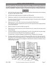
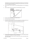
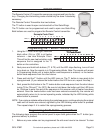
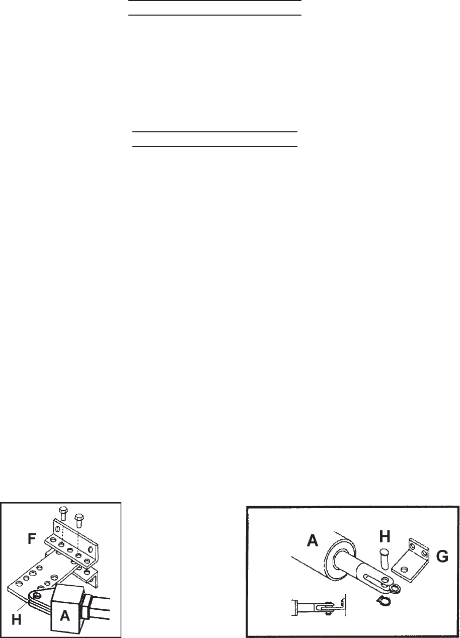
Mounting Actuator Arms
The placement of the Arm Mounting Brackets (F) on the gate support post or pillar will affect
the amount of gate opening, its speed, and force. Other factors include the weight and length
of the gate wing. The control board has two POT Switches MOT1, MOT2 (Ampere 1, 2 on
the circuit board) that allow the user to adjust the opening and closing force of motor 1 and 2
respectively. This feature will work in conjunction with the adjustable “K” plate.
The following steps describe, generally, the installation of the Arm Mounting Brackets (F),
The Actuator Arms (A), and the Pivot T-brackets (G). Each installation is different so some
modification to these steps may be necessary. Refer to the illustrations below.
1. Assemble the Arm Mounting Brackets (F) using the supplied hardware (F and H) as
shown below-left.
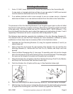
2. Place a Pivot Pin (H) through the rear bracket of the Actuator Arm (A) and the Arm
Mounting Brackets (F). Secure with the Pivot Pin (H), Washer, and Snap Lock from
beneath.
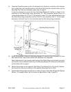
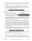
3. Place the Motor Disengage Key (I) (see page 19 assembly parts list) into the triangle
hole in the Actuator Arm (A) motor housing and turn it counterclockwise. This disengages
the motor so the Actuator Arm piston can be pulled out or pushed in.
4. Attach the Actuator Arm (A) piston to the Pivot T-bracket (G) using a Pivot Pin (H), Washer,
and Snap Lock from below. See illustration below-right.
5. Push the Actuator Arm (A) piston all the way in. See illustration below-right.
6. Open one Gate Wing to the desired opening (usually 90° as shown below, mid-page).
7. With the help of another person, hold up the Actuator Arm (A) with Arm Mounting brackets
(F) against the mounting post, and Pivot T-bracket (G) against the Gate Wing.