


SKU 47821 For technical questions, please call 1-800-444-3353 Page 10
14. Close the Gate Wing again, push in the Actuator Arm (A) piston, and hold up the Actuator
Arm against the new marked outline on the Wing Gate and the marked outline on the
Mounting Post. See the illustration under step 9, page 9.
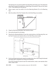
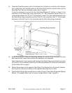
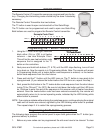
It may be necessary to move the Arm Mounting Bracket (F) farther or closer to the
centerline of the Gate Wing hinge (dimension “X”). See illustration below. There is a
relationship between the “X” and “Y” dimensions, where “X” is the width dimension from
the Gate Wing hinge centerline and the Pivot Pin (H) centerline; And “Y” is the depth
dimension from the Pivot Pin (H) centerline and the Gate Wing hinge centerline.
15.
Guidelines:
Gate Wings under 5’ (W), X = 4”, Y = 4”
Gate Wings over 5’ (W), X = 5.5”, Y = 4.8”
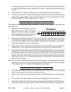
When the locations of the Arm Mounting Bracket (F) and the Pivot T-bracket (G) have
been determined, mount the brackets with hardware (not supplied).
Minor adjustments to the opening and closing of the Gate Wing can be made by moving
the Pivot Pin (H) to a different hole in the Arm Mounting Bracket (F). Refer to the illustration
at the bottom-left on page 8.
16. Repeat these steps for the opposite Gate Wing. The Actuator Arm (A) should, however,
be mounted in the same location on the opposite Mounting Post or Pillar.
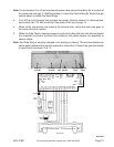
17. Test the Gate Wings. Both should move in and out freely. Close Gate Wings and Engage
Motors. (To engage Motors, do the reverse as described in step 3, page 8.)